Sound processing system

a processing system and sound technology, applied in the field of sound processing systems, can solve the problem that the specifications cannot be altered, and achieve the effect of optimal voice enhancement and sound communication, and low cos

Inactive Publication Date: 2014-11-11
YAMAHA CORP
View PDF20 Cites 26 Cited by
  • Summary
  • Abstract
  • Description
  • Claims
  • Application Information

AI Technical Summary

Benefits of technology

[0027]According to the present invention, the system is realized in a simplified configuration in which a plurality of sound emitting and collecting apparatuses are connected to each other via a transmission line. This makes it possible to construct at low cost an optimal system that fits with its service environment and provide optimal voice enhancement and sound communications.

Problems solved by technology

In the aforementioned sound enhancement system, the speakers and microphones are fixedly installed in the conference room, and thus their specifications cannot be altered once they are installed there.

Method used


Image

  • Sound processing system
  • Sound processing system
  • Sound processing system

Examples


Embodiment Construction

[0044]Now, a sound processing system according to an embodiment of the present invention will be explained with reference to the accompanying drawings. For example, the sound processing system is used in a sound enhancement system, a sound communication system, and a sound enhancement and sound communication system.

[0045](Sound Enhancement System)

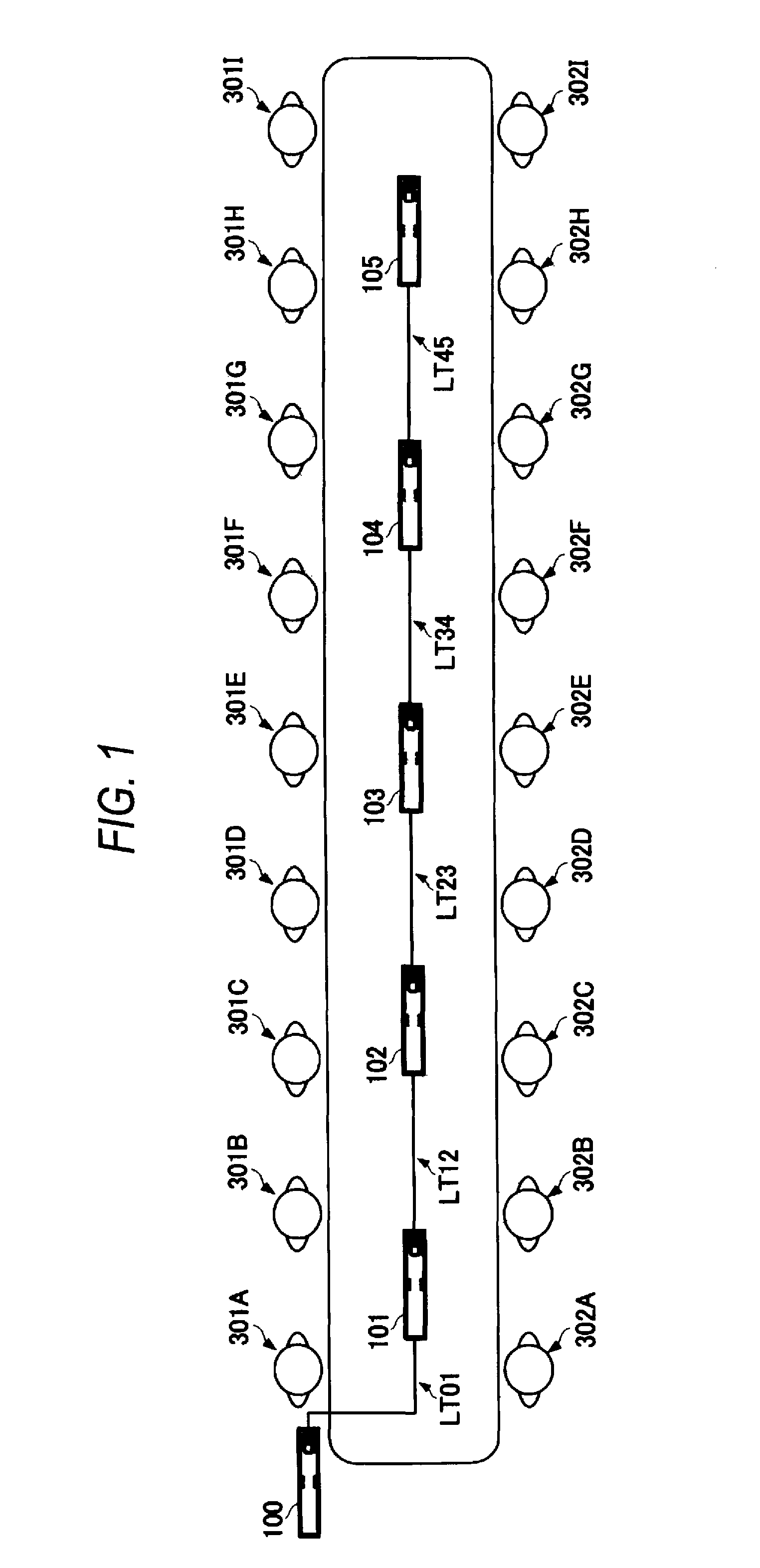
[0046]FIG. 1 is a block diagram illustrating the system configuration of a sound enhancement system of the present embodiment.

[0047]As shown in FIG. 1, the sound enhancement system includes sound emitting and collecting apparatuses 100 to 105 and transmission lines LT01, LT12, LT23, LT34, and LT45. The sound emitting and collecting apparatus 100 and the sound emitting and collecting apparatus 101 are connected to each other with the transmission line LT01. The sound emitting and collecting apparatus 101 and the sound emitting and collecting apparatus 102 are connected to each other with the transmission line LT12. The sound emitting and col...


PUM


Abstract

A sound enhancement system is configured such that sound emitting and collecting apparatuses 100 to 105 are connected to each other via a transmission line LT. The sound emitting and collecting apparatuses 100 to 105 are grouped into a master and a slave. The master sound emitting and collecting apparatus 100 generates a reference clock signal to be supplied to slave sound emitting and collecting apparatuses 101 to 105. The slave sound emitting and collecting apparatuses 101 to 105 form a sound collection beam signal in synchronization with the reference clock signal, and then output the resulting signal to the master sound emitting and collecting apparatus 100 without performing acoustic coupling suppressing process. The master sound emitting and collecting apparatus 100 collectively executes the acoustic coupling suppressing process to each sound collection beam signal to produce a sound emitting signal. The master sound emitting and collecting apparatus 100 outputs the sound emitting signal to the slave sound emitting and collecting apparatuses 101 to 105, each of which emits sound based on the sound emitting signal.

Description

[0001]This application is a U.S. National Phase Application of PCT International Application PCT / JP2008 / 068078 filed on Oct. 3, 2008 which is based on and claims priority from JP 2007-261897 filed on Oct. 5, 2007, the contents of which is incorporated herein in its entirety by reference.TECHNICAL FIELD[0002]The present invention relates to a sound processing system. More particularly, the invention relates to a sound enhancement system in which a plurality of sound emitting and collecting apparatuses, each having a microphone and a speaker, are placed in a predetermined space such as in the same room to enhance and transmit the collected sound. The invention also relates to a sound communication system which transmits a collected sound to an external sound emitting and collecting apparatus via a network or emits a sound emitting signal from the external sound emitting and collecting apparatus.BACKGROUND ART[0003]Conventionally, in a case where a number of conferees are present at th...

Claims


Application Information

Patent Timeline
Patent Type & Authority Patents(United States)
IPC IPC(8): H04M3/00H04R1/40H04M3/56H04R3/00G06F17/00
CPCH04M3/002H04R1/406H04R3/005H04R1/403H04M3/56
Inventor ISHIBASHI, TOSHIAKI
Owner YAMAHA CORP
Why Eureka
Try Eureka