Catenary line dynamic motion suppression

a technology of dynamic motion and catenary lines, applied in mechanical equipment, special-purpose vessels, transportation and packaging, etc., can solve the problems of increasing the dynamic bending stress, reducing the fatigue life of the line structure wherever, and the dynamic effects of the line used in offshore engineering can be very complex, and achieve good vortex induced vibration suppressors and low effective tension

Active Publication Date: 2014-11-18
WAJNIKONIS KRZYSZTOF JAN
View PDF14 Cites 3 Cited by
  • Summary
  • Abstract
  • Description
  • Claims
  • Application Information

AI Technical Summary

Benefits of technology

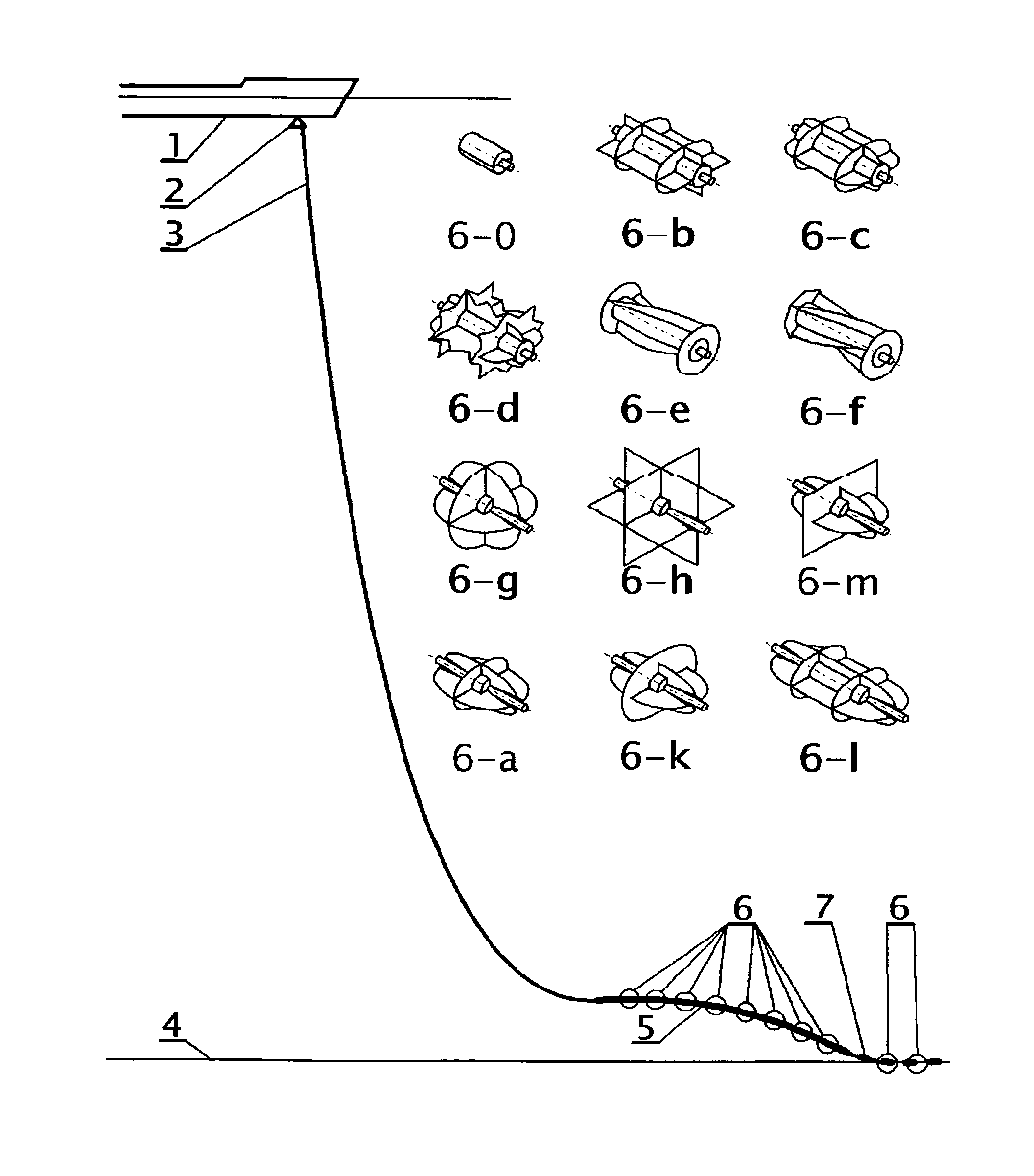
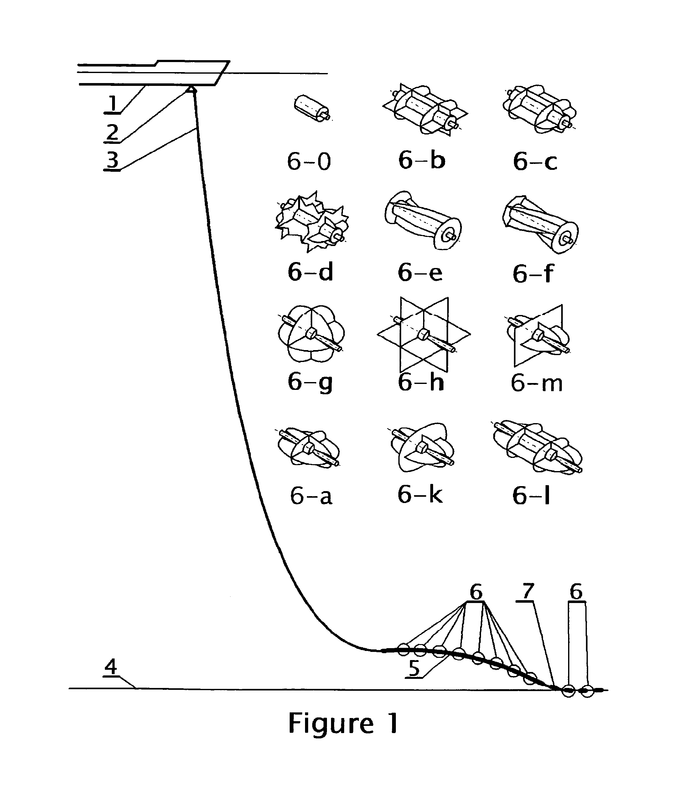
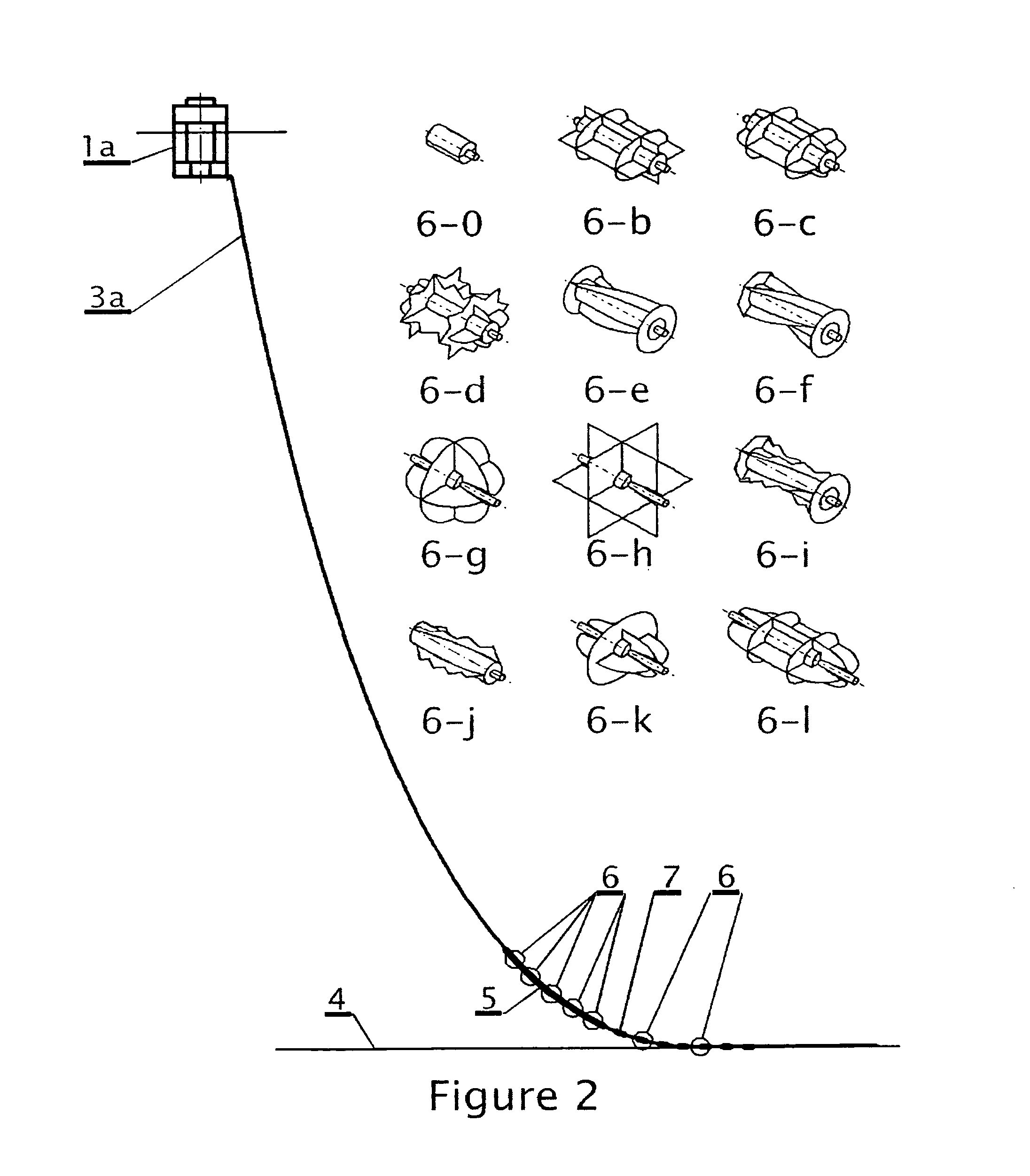
[0084]However, the average effective tensions at the top of the line segments between the distributed buoyancy in FIG. 1 (5) or distributed submerged weight in FIG. 2 (5) in these novel designs are significantly lower than those at the line hang-offs.

Problems solved by technology

The design issues particularly relevant to line engineering are:Dynamic bending, involving high dynamic bending stresses, particularly in the TDZ; any increase in the dynamic bending stresses reduces the fatigue life of the line structure wherever it occurs.Dynamic axial loads that also reduce the fatigue life wherever they cause dynamic stresses.Reductions in the dynamic tension, which includes dynamic line compression with a possibility of buckling or bird-caging of the line.
Currents are seldom uniform along said lines.
Dynamic effects on lines used in offshore engineering can be very complex.
It is often the case that the effective tension near the touch-down becomes periodically negative, making the line susceptible to local buckling, which usually is not desirable and sometimes it is completely unacceptable (example fiber-optic lines).
Bird-caging of umbilical or cable lines can occur, rigid or flexible pipes usually have some built-in resilience, but complex local increases in fatigue damage typically result.
Often, in presently known designs it is difficult to increase the effective tension and to increase the minimum dynamic bending radii to acceptable levels.
Increasing the horizontal tension in the catenaries, which increases also the quasi-static, average effective tension at the touch-down in many known designs is known to often make the dynamic effects described above even worse.
In particular, the said touch down zone line dynamics is in presently known designs both significant and troublesome for simple, free hanging catenary lines attached to floating structures.
In particular, at present, it might be not possible to use larger diameter single pipe or Pipe-in-Pipe (PIP) SCRs on some fields, where smaller diameter freehanging configurations are at present used.
This is because the selection of a simple (freehanging) catenary configuration would have resulted in very high hang-off loads.
These would have become even higher in a case of an accidental flooding of the line with seawater that might inadvertently happen during installation or in operation.
In such cases using a freehanging catenary might be impossible, because the excessive hang-off load resulting might be too high to handle.
Similarly, there might be no installation vessel available anywhere in the world, to handle such a heavy pipe during its installation; or in particular to handle such a large diameter pipe or Pipe-In-Pipe, in a case of an accidental flooding with seawater.
However, it is noted that:The use of the configurations in question, as implemented in prior art, results in the increase of the suspended lengths used (and in the corresponding increase in costs of the installation that adds to the cost of the associated ‘additional’ hardware used);The selection of one of these configurations in prior art is because of one of the underlying reasons listed above; in the prior art these line configurations are, not selected because of the said added advantage.
This method tends to be only partially effective, because this makes the catenary above the clump weight steeper and it can result in the heave motions being transferred more easily down to the location of the clump weight.

Method used


Image

  • Catenary line dynamic motion suppression
  • Catenary line dynamic motion suppression
  • Catenary line dynamic motion suppression

Examples


Embodiment Construction

[0092]This invention allows the designer to locally fine tune several physical properties of lines, so that the desired motion suppression effect is achieved. The key line physical properties involved are the following:[0093]Mass per unit length,[0094]Added mass per unit length (described in terms of the added mass coefficient),[0095]Submerged weight and buoyancy per unit length,[0096]Drag coefficient.

The above combined properties of the line, on which known or / and novel devices are mounted combined with the properties of the said devices are of importance herein.

[0097]The above properties affect the statics and dynamics of said lines in complex ways that have been outlined with regard to the prior art pertaining to the use of clump weights and buoyancy. This invention extends the tools available to the designer by allowing more control over the remaining physical properties of said line, as well as more flexibility in shifting between the added and the actual mass per unit length a...


PUM


Abstract

This invention introduces three-dimensional (3D) damper arrangements that are used to suppress dynamic motions of a subsea line like a riser, on which the dampers are installed. Damping surfaces (shapes) are mounted on the line so that their combined drag per line unit length dampens motions in 3 mutually perpendicular directions: axial, in-plane (IP) and out-of-plane (OOP). 3D suppression is provided by integral 3D dampers or by combining IP-OOP dampers like strakes with neighboring axial dampers. Increased line motions suppression is achieved by decoupling, particularly on dampers mounted in regions of high line curvature and / or small effective tension. This invention also presents Short Lazy Wave (SLW) configurations of rigid catenary risers, which are also used to suppress dynamic motions. 3D dampers can be used together with SLWs. Motion suppression is introduced to reduce dynamic stresses and to increase fatigue life of the lines.

Description

CROSS-REFERENCE TO RELATED APPLICATIONS[0001]This application claims the priority of U.S. Provisional Patent Application Ser. No. 60 / 593,269 filed Jan. 3, 2005 and entitled: “Catenary Line Dynamic Motion Suppression Arrangement” the disclosure of which is hereby incorporated by reference in its entirety. This application is being filed in continuation to Utility patent application Ser. No. 11 / 813,162 filed Oct. 9, 2007, now abandoned.BACKGROUND OF THE INVENTION[0002]1. Field of the Invention[0003]This invention relates to lines used to connect subsea equipment to related equipment at or near the sea surface.[0004]2. Description of the Related Art[0005]Petroleum exploration and production is increasingly being conducted off-shore and at ever deeper locations. Typically, a mobile offshore drilling unit (“drilling rig”) is used to create a well. Once the well is completed, a production platform or a buoy is installed at the site to recover the petroleum products which may subsequently ...

Claims


Application Information

Patent Timeline
Patent Type & Authority Patents(United States)
IPC IPC(8): B63B22/18
CPCB63B22/18F16L1/123F16F7/10
Inventor WAJNIKONIS, KRZYSZTOF, JAN
Owner WAJNIKONIS KRZYSZTOF JAN
Why Eureka
Try Eureka