Holographic projection real-time 3D display system and method

a display system and real-time 3d technology, applied in the field of real-time 3d display systems, can solve the problems of complex implementation process, inconvenient viewing glasses, and human beings still far from realizing the super

Active Publication Date: 2014-11-18
AFC TECH
View PDF9 Cites 2 Cited by
  • Summary
  • Abstract
  • Description
  • Claims
  • Application Information

AI Technical Summary

Benefits of technology

[0015]The holographic functional screen is placed on the reference surface PR, and is used to perform spatial spectrum stretching corresponding to the spatial sampling angles ωmn on input information of the view Imn carried in each single spatial spectrum, so that after the stretching, output spatial spectrum distributions of the views Imn are connected to each other, but do not overlap, thereby ensuring that a digital holographic spatial spectrum of the restored 3D spatial information is restored and output continuously and completely. That is, for each hoxel Hjk on the holographic functional screen, a stretching angle of a spatial unidirectional input light beam is exactly the spatial sampling angle ωmn, thereby achieving holographic 3D display intended to restore complex wavefronts.
[0017]The capturing units of the photographing and capturing device respectively correspond to the projection units of the projective restoration device one by one. Image information captured by each capturing unit may be directly or indirectly transferred to the projection unit corresponding to the capturing unit in any digital image transmission format, without having to essentially code and reorganize the specific image information.
[0022]The limited stretching process of the holographic functional screen comprises the following steps. The holographic functional screen is placed on the reference surface PR, so as to perform spatial spectrum stretching corresponding to the spatial sampling angles ωmn on input information of the view Imn carried in each single spatial spectrum, so that after the stretching, output spatial spectrum distributions of the views Imn are connected to each other, but do not overlap, thereby ensuring that a digital holographic spatial spectrum of the restored 3D spatial information is restored and output continuously and completely. That is, for each hoxel Hjk on the holographic functional screen, a stretching angle of a spatial unidirectional input light beam is exactly the spatial sampling angle ωmn, thereby achieving holographic 3D display intended to restore complex wavefronts.
[0023]The capturing units in the capturing process respectively correspond to the projection units in the projective restoration process one by one. Image information captured by each capturing unit may be directly or indirectly transferred to the projection unit corresponding to the capturing unit in any digital image transmission format, without having to essentially code and reorganize the specific image information.

Problems solved by technology

Although the practical applications of 3D cinemas and lens board 3D photos in the middle of the last century marked a certain breakthrough, human beings are still far away from effectively realizing the super dream of moving visual space, that is, vividly transferring and displaying 3D information of the nature.
The implementation process is complicated.
Sometimes, special inconvenient glasses are required for viewing.
However, the holography is still far from color real-time holographic 3D visual space moving and displaying.
However, the digital holography is so far still limited to the printing and displaying of holograms.
However, none of the solutions is further developed due to the subjective visual processing manner of the issue and lack of proper theoretical support and experimental conditions.
However, like the films and TV programs, all the methods use the effect of persistence of vision to realize 3D display by scanning and outputting spatial 3D information in a time-sharing manner, and therefore the TV set is not a real holographic TV set showing TV information in a holographic manner in the strict sense.
Limited by a spatial bandwidth product of the conventional SLM, the methods are obviously far from practical application, and increase of the spatial bandwidth product is ultimately restricted by the so called Moore's Law manifesting integration capability of electronic chips.
In an article “An updatable holographic three dimensional display”, recently published in Nature, Vol. 451 / 7 February 2008 / 694-698, a holographic TV set seems about to come true, but the practical application of the new holographic material is still inconceivable.
The 2D image information can only enable us to learn one side of an object, which to a great extent prevents the humans from learning the essence of the object comprehensively.

Method used


Image

  • Holographic projection real-time 3D display system and method
  • Holographic projection real-time 3D display system and method
  • Holographic projection real-time 3D display system and method

Examples


Embodiment Construction

[0090]The present invention is further described below in detail with reference to embodiments and the accompanying drawings.

[0091]Embodiments of the present invention are made based on new theories, and theories related to the embodiments of the present invention are illustrated before the embodiments are described.

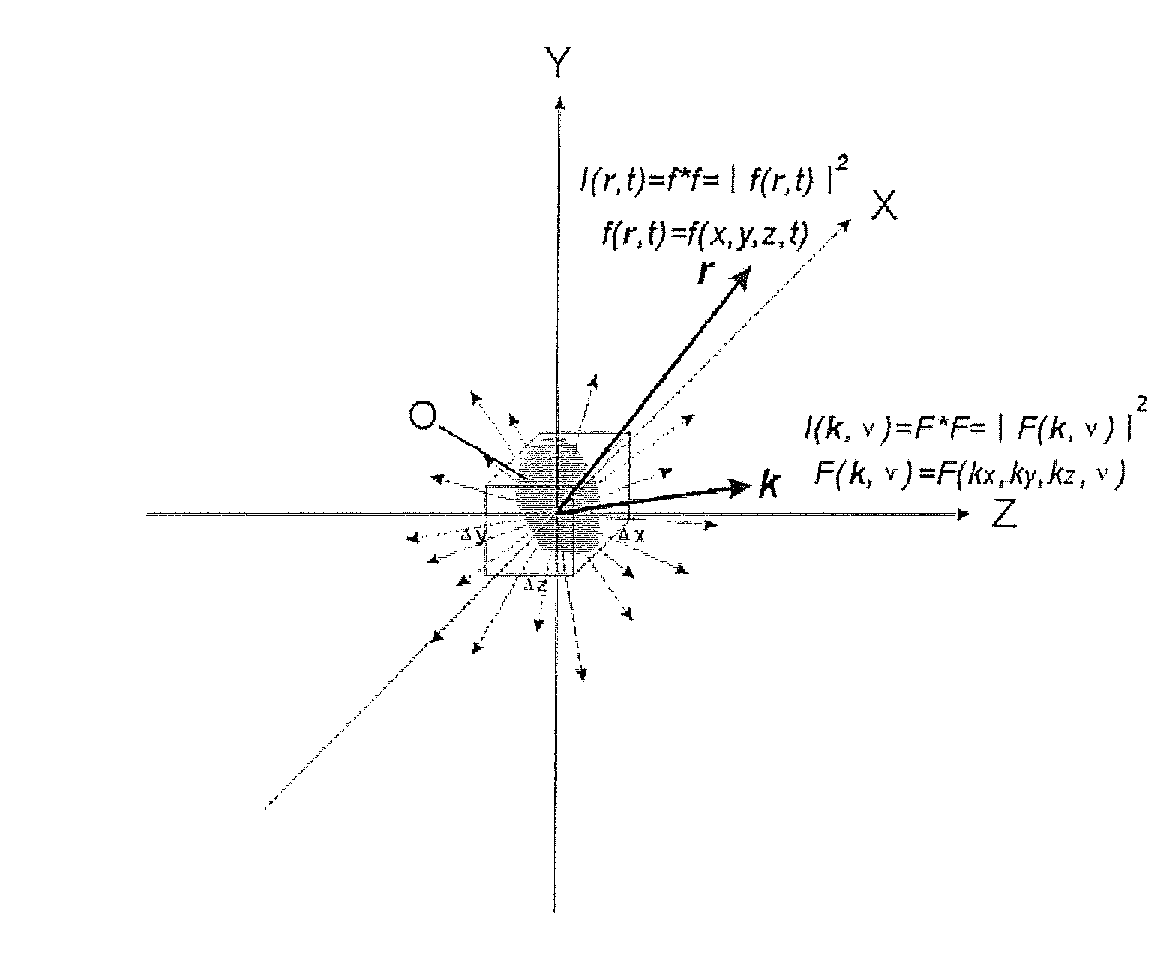
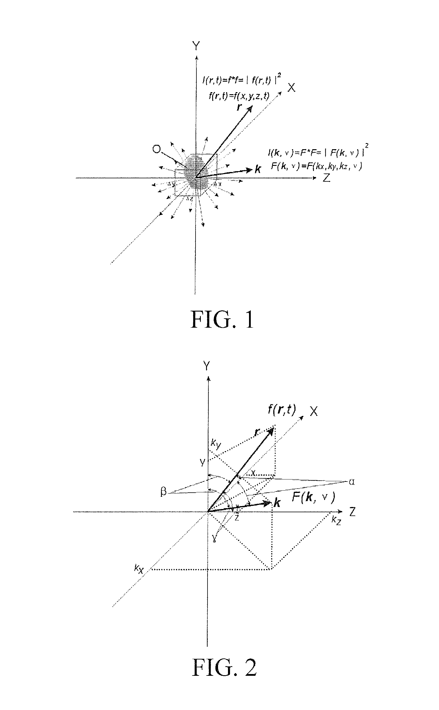
[0092]I. Four-Dimensional (4D) Fourier Transform of Wave Function

[0093]Light is formed of photons. Each photon has the minimum electromagnetic radiation energy thereof satisfying ε=hv, where h is the Planck constant and satisfies h=6.626×10⁻³⁴ J·S, v is a vibration frequency of the photon whose wavelength satisfies λ=c / v, and c is the speed of light, which is in vacuum a constant c=2.997 924 58×108 m / s. A corresponding momentum of the photon satisfies p=hk, where k is a propagation vector, and satisfies k=1 / λ. The above is consistent with the special theory of relativity, and a relationship among the mass, energy, and momentum of the particle herein satisfies ε=[(cp)2+(m...


PUM


Abstract

A real-time color holographic three-dimensional (3D) display system and method realized by using principles of digital holographic display and a common photographing / projection device array system are provided. For an object O to be displayed, an array of M×N cameras which are anchored to a certain reference point R in a space corresponding to the object O is used to perform spatial spectrum sampling and capturing on any spatial spectrum surface S of the object O with a sampling density being a spatial sampling angle ωmn. Each acquired spatial spectrum view image Imn is projected by a corresponding array of M×N projectors in each spatial spectrum capturing direction to a reference surface PR necessary for restoring 3D information of the original object O. Output of full spatial spectrums of the object O is realized through a spatial spectrum limited stretching function of a holographic functional screen placed on the reference surface PR which is used on discrete spatial spectrum input image information, thereby achieving digital holographic display intended to restore complex wavefronts.

Description

BACKGROUND OF THE INVENTION[0001]1. Field of the Invention[0002]The present invention relates to a real-time 3D display system realized by using holographic projection, which comprises a capturing device, a projection device, and a display for a real-time 3D image, and relates to a real-time 3D display method, a real-time 3D image capture method, a projection display method, and a display manufacturing method.[0003]2. Related Art[0004]Chinese Patent No. ZL200410022193.7 entitled “METHOD AND DEVICE FOR MAKING DIGITAL SPECKLE HOLOGRAM”, and Chinese Patent No. ZL200510022425.3 entitled “HOLOGRAPHIC PROJECTION SCREEN, AND MANUFACTURING METHOD, SYSTEM, AND APPLICATION THEREOF” are incorporated herein by reference in their entireties.[0005]Since the beginning of the last century, scientists never stop the search for a proper method to solve the “3D imaging” problem. Although the practical applications of 3D cinemas and lens board 3D photos in the middle of the last century marked a certai...

Claims


Application Information

Patent Timeline
Patent Type & Authority Patents(United States)
IPC IPC(8): G03H1/04G02B27/22H04N13/02H04N15/00G03H1/02G03B35/08H04N13/04G03B35/18
CPCG02B27/2278G03H2001/0288G03H1/04G03B35/18H04N13/0242H04N13/0447G03H2224/02H04N13/0459G03H2001/0439G03B35/08G02B30/52H04N13/243H04N13/351H04N13/363
Inventor FAN, CHENGCAI, ZHISENJIANG, CHAOCHUAN
Owner AFC TECH
Why Eureka
Try Eureka