Defective recording element detecting apparatus and method, and image forming apparatus and method

a recording element and detection apparatus technology, applied in the field of defective recording element detection apparatus and method, image forming apparatus and method, can solve the problems of recording position error, image streaky artifacts in images recorded on recording media, etc., to achieve accurate identification

Inactive Publication Date: 2014-11-18
FUJIFILM CORP
View PDF6 Cites 26 Cited by
  • Summary
  • Abstract
  • Description
  • Claims
  • Application Information

AI Technical Summary

Benefits of technology

[0019]The present invention has been contrived in view of these circumstances, an object thereof being to provide defective recording element detecting apparatus and method and image forming apparatus and method which uses the detection technique which are capable of accurately identifying a defective recording element even when distortion occurs in a test pattern read image.
[0021]According to this aspect of the present invention, even if the read image of the test pattern is distorted, the distortion can be effectively corrected and a defective recording element can be accurately identified from the test pattern recording result. In particular, since the correlation operation is performed on the basis of the read image data to determine the distortion correction value, even irreproducible image distortion can be favorably corrected.
[0032]According to this aspect of the present invention, data for the shading correction (distribution information that indicates shading characteristics) is obtained from the image area of the test pattern for detecting the defective recording element to perform the shading correction. As a result, even irreproducible shading can be favorably corrected. The shading correction and the image distortion correction combine with each other to enable detection of the defective recording element at an even higher accuracy.
[0037]According to this aspect of the present invention, by adopting the configuration of the image forming apparatus that is provided with the image reading device and the analyzing function of the image read by the image reading device, the test chart can be outputted and, at the same time, the output result can be read. As a result, efficient analysis, identification of the defective recording element on the basis of the analysis, and image correction according to a result of the identification can be performed.
[0044]According to the present invention, even when the test pattern read image is distorted, a defective recording element can be accurately identified from the read image.

Problems solved by technology

However, with a full-line head image forming apparatus, an actual dot position that is actually recorded on a recording medium can be rendered deviated from an ideal dot position due to various reasons such as production tolerance, deterioration with age, or the like of recording elements (including nozzles) constituting the ejection unit, and the deviation causes a recording position error (droplet deposition position error).
As a result, a problem arises in that streaky artifacts occur in an image recorded on the recording medium.
In addition to artifacts due to such a recording position error, there are phenomena in which streaky artifacts occur in an image recorded on the recording medium due to failures in a recording element such as an abnormality in which droplets are not ejected (non-ejection), an abnormality in ejection volume, and an abnormality in ejection shape (e.g., splash).
With such a large number of recording elements, defective nozzles can occur at various timings.
More specifically, a nozzle can become defective at the time of manufacture of a recording head, a nozzle can become defective due to deterioration with age, a nozzle can become defective during maintenance (when a nozzle suffers maintenance-induced defectiveness, the nozzle is often restored by a next maintenance), and a nozzle can become defective midway through continuous printing.
Moreover, with the technique described in the publication, a sufficiently accurate detection result cannot be obtained under a condition where a width of a line formed by dots on a test pattern does not satisfy a sampling theorem, since a certain amount of error (an estimation error of a line profile formed by dots) remains on an identified line position.
However, disposing the correction pattern additionally to the detection pattern as described in the publication increases used area in the recording sheet and problematically increases area in the recording sheet that is worthless from a user's perspective.
(2) A vibration of the apparatus or the like can cause an image reading optical system to sway and can generate swaying or winding of a line on the read image which reflects the vibration.
Such distortion of read images lowers a detection accuracy of defective nozzles.
Therefore, such irreproducible distortion and light intensity fluctuation (shading) are fluctuation factors that are difficult to correct using a fixed correction table or the like.

Method used


Image

  • Defective recording element detecting apparatus and method, and image forming apparatus and method
  • Defective recording element detecting apparatus and method, and image forming apparatus and method
  • Defective recording element detecting apparatus and method, and image forming apparatus and method

Examples


Embodiment Construction

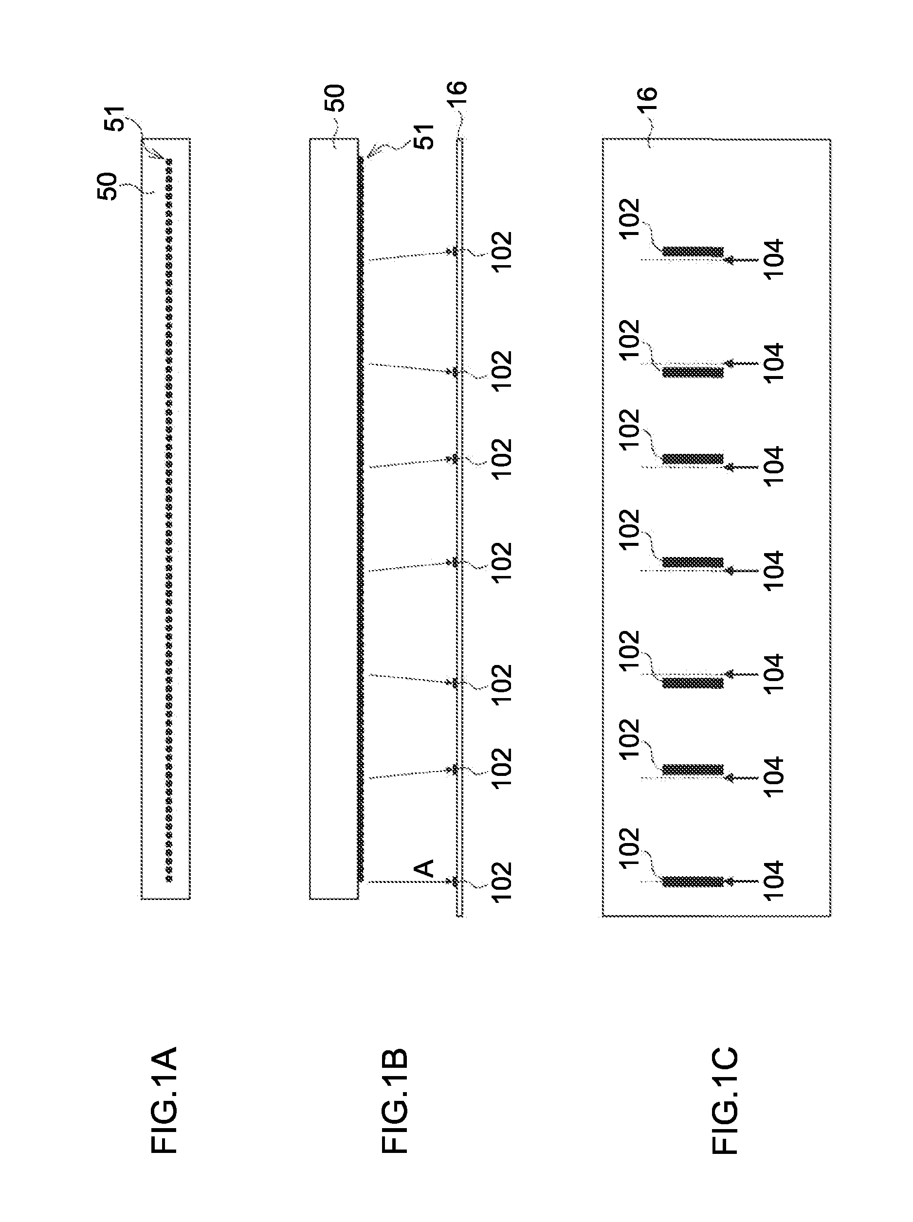
[0083]Errors in droplet deposition positions (recording positions) are described as examples of errors rendered by defective nozzles. FIGS. 1A to 1C are diagrams that schematically illustrate a state where deposition positions of ink droplets ejected from nozzles are deviated from ideal deposition positions on a recording medium. FIG. 1A is a plan view showing a line alignment of a plurality of nozzles 51 in a head 50. FIG. 1B is a diagram in which a state where ink droplets are ejected from nozzles 51 toward a sheet of recording medium or paper (hereinafter referred to as a “recording sheet”) 16 is viewed from a lateral direction. Arrows A in FIG. 1B schematically show the ejection directions of ink droplets from the nozzles 51. FIG. 1C is a diagram showing examples of test patterns 102 formed on the recording sheet 16 by the ink droplets which have been ejected from the nozzles 51 and deposited on the recording sheet 16, wherein the ideal deposition positions 104 are shown with da...


PUM


Abstract

A defective recording element detecting apparatus includes: a read image data acquiring device which acquires read image data of a test pattern recorded on a recording medium by a recording head having recording elements; a reference area setting device which sets a reference area including a part of the test pattern on a read image representing image contents of the read image data; a comparison area setting device which sets a comparison area on the read image; a correlation operation device which performs a correlation operation between the comparison area and the reference area; a distortion correction value determining device which determines a distortion correction value, from a result of the correlation operation; an image distortion correcting device which corrects image distortion of the read image using the distortion correction value; and a defective recording element determining device which identifies a defective recording element according to the corrected read image.

Description

BACKGROUND OF THE INVENTION[0001]1. Field of the Invention[0002]The present invention relates to a detection technique of identifying a defective recording element among a plurality of recording elements in a recording head (for example, an inkjet head) by means of a result of test pattern recording by the recording head, and an image forming technique to which the detection technique is applied.[0003]2. Description of the Related Art[0004]Methods of recording an image on a recording medium such as a sheet of recording paper (hereinafter referred to as a “recording sheet”) include an inkjet image forming system in which ink droplets are ejected from a recording head in accordance with an image signal and the ejected ink droplets are deposited onto the recording medium. An example of an image forming apparatus using such an inkjet image forming system is a full-line head image forming apparatus in which an ejection unit (including a plurality of nozzles) that ejects ink droplets is l...

Claims


Application Information

Patent Timeline
Patent Type & Authority Patents(United States)
IPC IPC(8): H04N1/46B41J2/21H04N1/60B41J29/393B41J29/38B41J2/205G06K15/10
CPCB41J2/2146B41J2/2142H04N1/4076H04N1/4015B41J2/2139
Inventor YAMAZAKI, YOSHIROU
Owner FUJIFILM CORP
Why Eureka
Try Eureka