Optical switching apparatus and method for an eNB
a technology of optical switching and optical switch, applied in the field of data communication, can solve the problems of limited connection number, further affecting application, and limited optical communication links between, and achieve the effect of enabling the expansion of the transmission distan
- Summary
- Abstract
- Description
- Claims
- Application Information
AI Technical Summary
Benefits of technology
Problems solved by technology
Method used
Image

Examples
Embodiment Construction
[0036]Function Overview
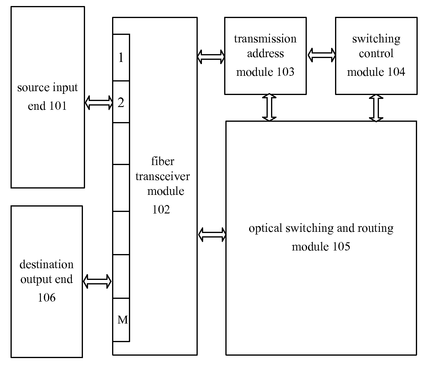
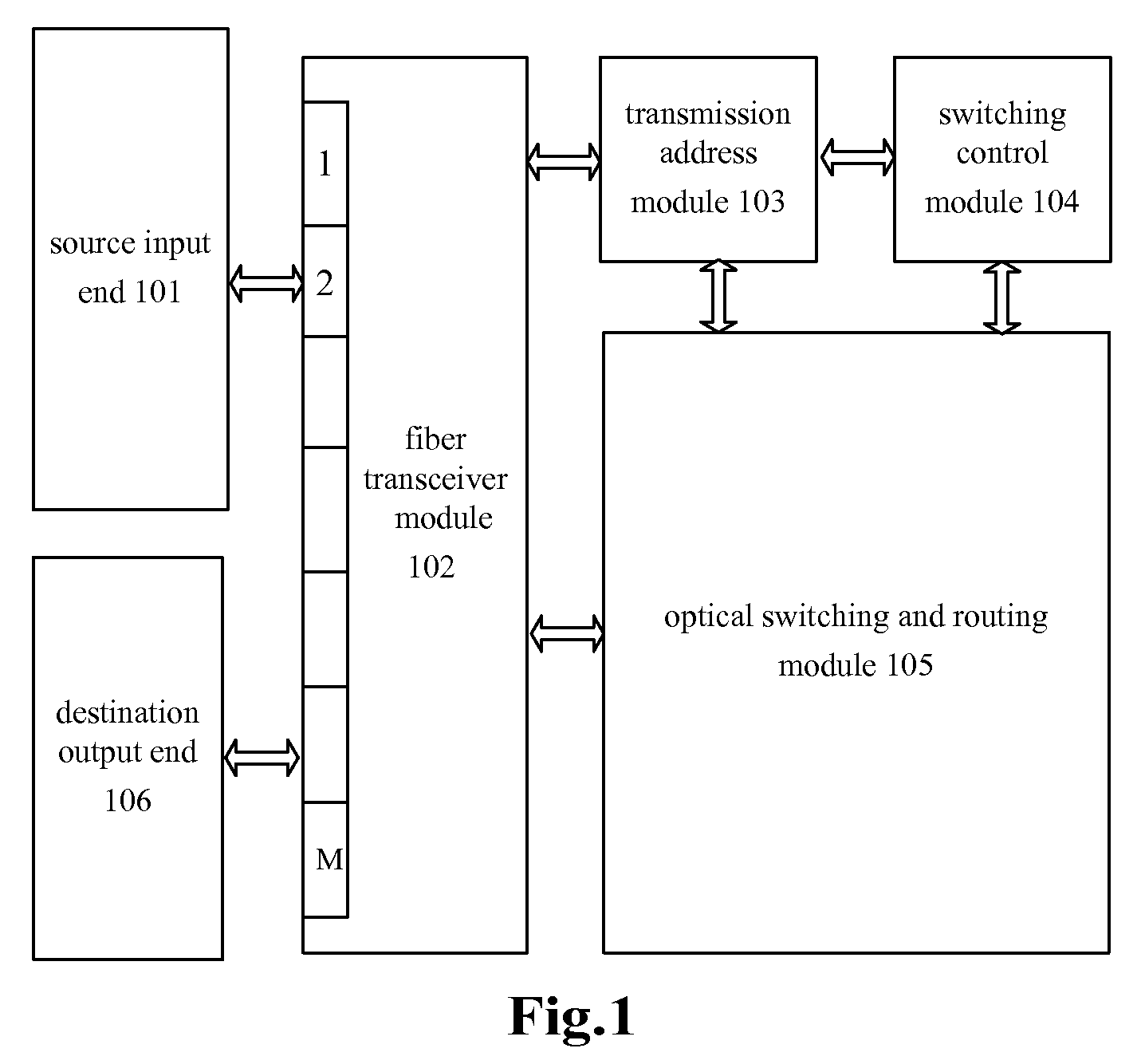
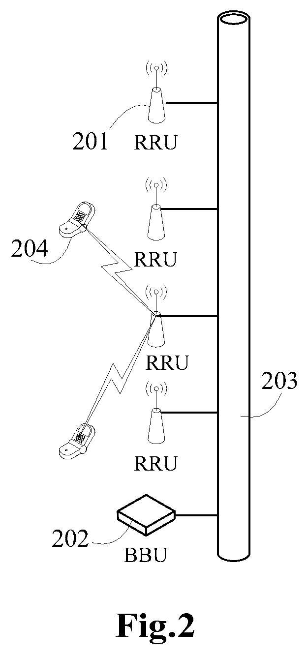
[0037]In the embodiments of the present invention, by an optical switching apparatus and method of the eNB, the network topology structure between a BBU and a RRU of an eNB can be changed from a direct connection network to a switching network; the networking can be flexible; a separate communication and a multiple-to-multiple communication are realized; the BBU and the RRU of the eNB can communicate with device(s) of the RRU and the BBU of a different manufacturer; and specifically, the apparatus and the method can be applied to a multi-mode base station, wherein the BBU and the RRU can adapt to different modes and the transmission distance is enlarged.
[0038]The present invention will be further described in connection with the drawings and the embodiments in order to understand the present invention better.
[0039]The embodiments of the application and the features thereof can be combined with each other if there is no conflict.
[0040]As shown in FIG. 1, when a...
PUM
 Abstract
Description
Claims
Application Information
 - R&D
- Intellectual Property
- Life Sciences
- Materials
- Tech Scout
- Unparalleled Data Quality
- Higher Quality Content
- 60% Fewer Hallucinations
Browse by: Latest US Patents, China's latest patents, Technical Efficacy Thesaurus, Application Domain, Technology Topic, Popular Technical Reports.
© 2025 PatSnap. All rights reserved.Legal|Privacy policy|Modern Slavery Act Transparency Statement|Sitemap|About US| Contact US: help@patsnap.com