Adjustable socket

a technology of adjustable sockets and jaws, applied in the field of adjustable sockets, can solve the problems of reducing the force potential, limiting the effectiveness and range of operation of adjustable sockets, and limiting the operation range of adjustable sockets whose paths travel in direct radial paths to the fastener, so as to increase the operable range of adjustable sockets, reduce slippage, and increase the effect of force potential

Inactive Publication Date: 2014-11-25
WOMACK BRETT
View PDF28 Cites 19 Cited by
  • Summary
  • Abstract
  • Description
  • Claims
  • Application Information

AI Technical Summary

Benefits of technology

[0005]An adjustable socket with jaws that travel along paths oblique to the center of the socket can overcome the limitations presented by adjustable sockets with radially-moveable jaws. These oblique pathways can be longer than a corresponding radial pathway, thereby increasing the operable range of the socket. Jaws that travel along oblique pathways may slide past one another rather than contract together, allowing for a jaw of maximum possible width. This in turn creates more shared surface area between socket and fastener, increasing force potential and reducing slippage. Furthermore, jaws that slide past one another provide additional resistance against undesired rotation or tilting of the jaws by buttressing one another at the points of greatest pressure.
[0006]A well-designed adjustable socket is a simple, convenient, cost-effective alternative to a socket set, allowing for a wide range of adjustable sizes, providing the ability to apply and maintain significant force to a fastener without slipping or failing, while maintaining a sleek, aesthetic design. These qualities are included in the embodiments of the adjustable socket described below.

Problems solved by technology

However, despite the basic functionality of these devices, they are susceptible to inherent design restrictions that limit their effectiveness and range of operation.
The operating range of an adjustable socket with jaws whose pathways travel in a direct radial path toward the fastener is inherently limited.
These conditions result in less shared surface area between the sockets and fasteners, which results in reduced force potential and increased slippage.

Method used


Image

  • Adjustable socket
  • Adjustable socket
  • Adjustable socket

Examples


Embodiment Construction

[0044]The following description contains concise, exact details to provide any person skilled in the art a clear and thorough understanding of the instrument described herein. Well-known elements may not be described in detail, however, to avoid unnecessary complication of the description and associated illustrations. Furthermore, the described embodiments and associated illustrations are intended to be exemplary and not restrictive, as modifications or refinements to the preferred embodiments may occur.

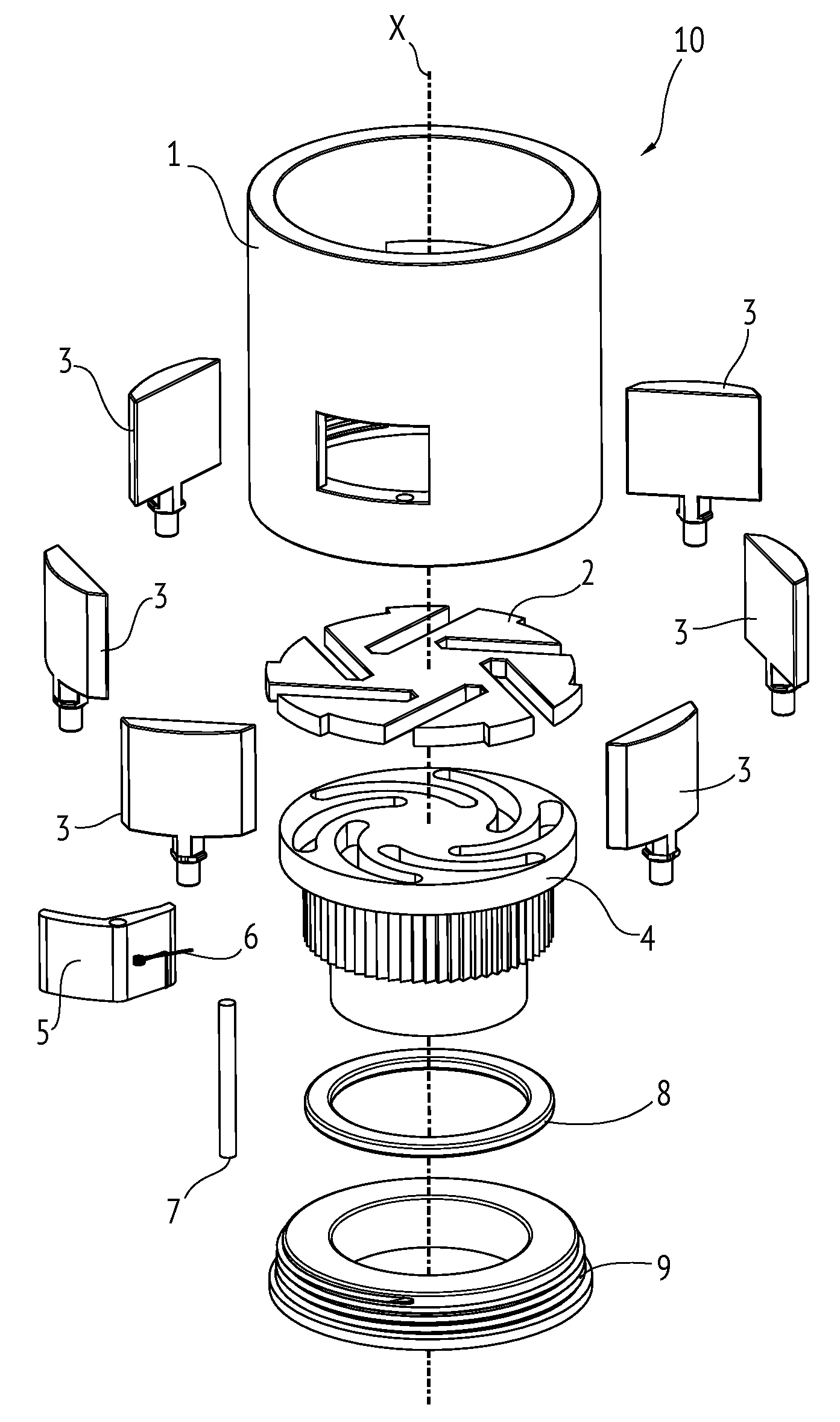
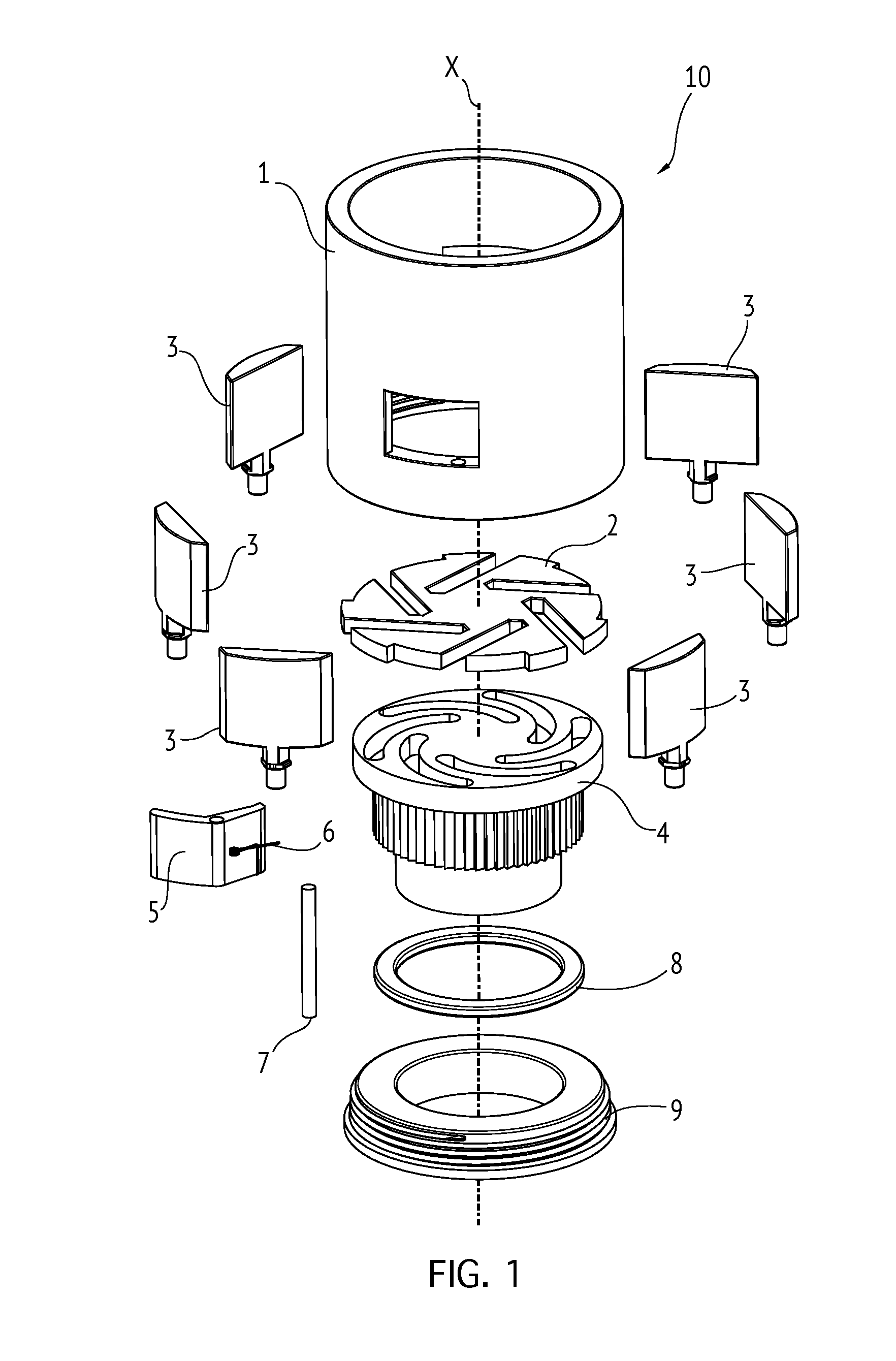
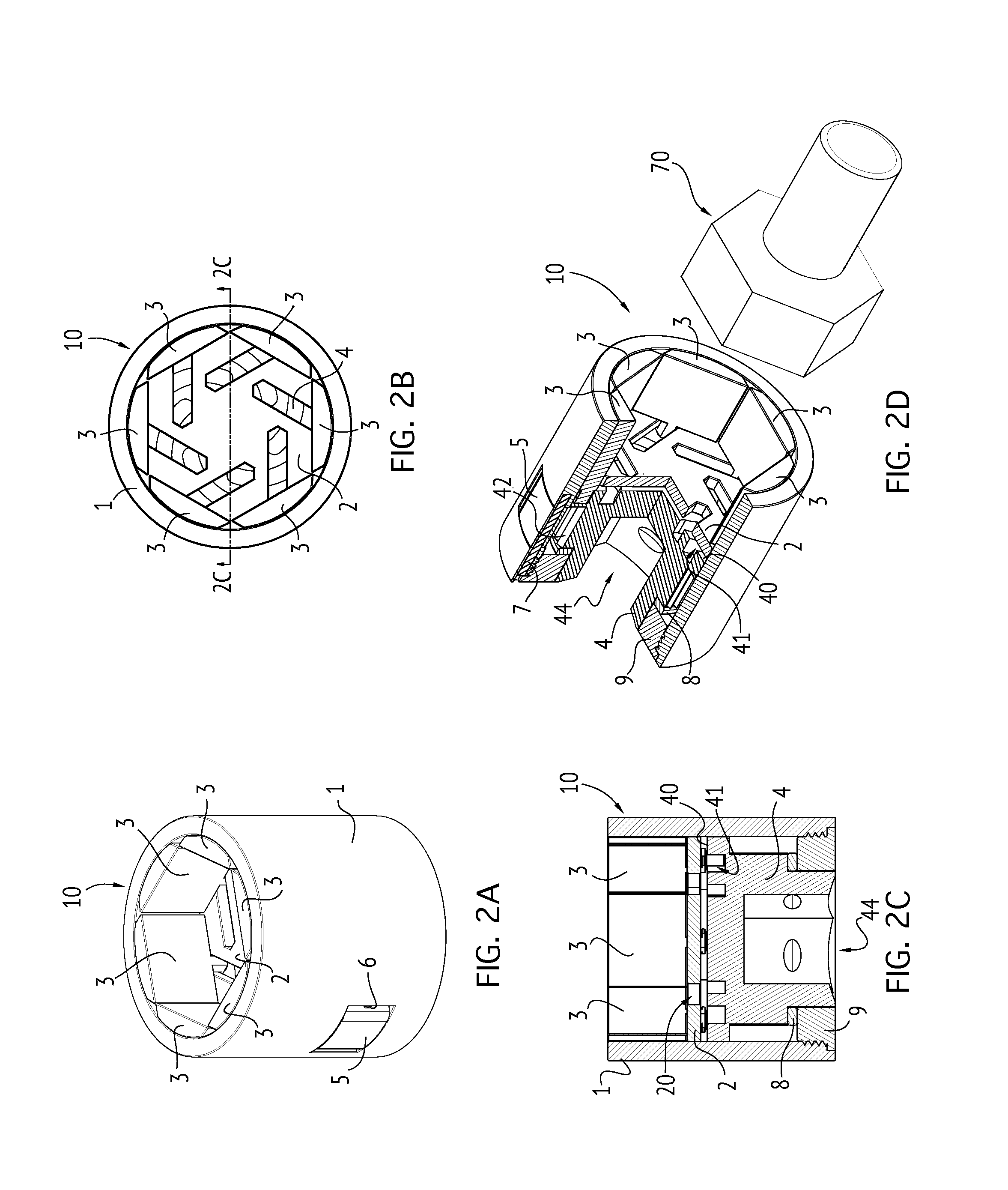
[0045]FIGS. 1 and 2A-2D depict an adjustable socket 10 comprising a housing 1, a disc 2, a plurality of jaws 3, a drive core 4, a locking lever 5 with biasing torsion spring 6 and pin 7, a washer 8, and a threaded plug 9.

[0046]Housing 1 (also shown separately in FIGS. 3A-3C) is generally circular in cross-section, and possesses a generally cylindrical shape aligned along a longitudinal axis X. Three locking grooves 11, sized and shaped to couple with disc 2, extend longitudinally alo...


PUM


Abstract

An adjustable socket including a housing designed on a longitudinal axis, with a series of grooves extending longitudinally along the interior wall. A disc with guide slots intruding obliquely off-center from the perimeter is locked into position within the housing. Jaw members with bottom stems and cams are mounted in the disc guide slots, free to move laterally along fixed paths. An axially rotatable drive core with a cam surface is positioned within the housing, engaging the cam of each jaw. Rotation of the drive core forces the jaws to travel inwardly along the disc guide slots as dictated by the spiraling guide elements of the cam surface, to be forced against a fastener within the jaws. A locking mechanism holds the jaws in position on the fastener. Release of the locking mechanism allows rotation of the drive core in the opposite direction to release the fastener.

Description

RELATED APPLICATION[0001]This application is a utility patent application based on U.S. provisional patent application No. 61692996, filed on Aug. 24, 2012, entitled “Adjustable Socket”, which is incorporated herein by reference and made a part of this application.BACKGROUND OF THE INVENTION[0002]An adjustable socket that can fit varying sizes of fasteners (nuts, bolts, etc.) can replace several fixed-size sockets, reducing the components of a socket set into a minimal number of tools. An adjustable socket allows for streamlining of workflow, as time is no longer spent finding and selecting the correct fixed-size socket from a set. An adjustable socket may also more tightly grip a damaged or worn fastener than a fixed-size socket.[0003]Several adjustable sockets exist in the prior art which are manually adjustable to fit varying sizes of fasteners, by means of a plurality of jaws which are moveable along a fixed path. However, despite the basic functionality of these devices, they a...

Claims


Application Information

Patent Timeline
Patent Type & Authority Patents(United States)
IPC IPC(8): B25B13/12B25B13/20B25B13/06B25B13/18
CPCB25B13/12B25B13/06B25B13/18B25B13/20
Inventor WOMACK, BRETT
Owner WOMACK BRETT
Why Eureka
Try Eureka