Screw method for forming a screw thread

a screw thread and screw technology, applied in the field of screw threads, can solve the problem that the two ridges of material cannot be completely joined, and achieve the effect of improving the resistance to wear and tear

Active Publication Date: 2014-12-02
HILTI AG
View PDF24 Cites 5 Cited by
  • Summary
  • Abstract
  • Description
  • Claims
  • Application Information

AI Technical Summary

Benefits of technology

[0005]It is an object of the invention to provide a screw, especially a self-cutting screw, that exhibits considerably better resistance to wear and tear. It is also an object of the invention to provide a method for the production of such a screw.
[0006]In order to achieve the objective with a screw of the above-mentioned type, it is provided that the closing crease is situated in the area of a flank of the thread. In the prior-art methods, in a manner of speaking, the ridges of material are pushed together towards the center of the thread uniformly from both sides, which simplifies the production since it is possible to keep the profiling of the rolling dies very simple since the highest point of the thread also corresponds to the transition site between the two ridges of material. In other words, each of the profiles only has to form one of the two flanks of the thread. Consequently, the weak spot in the material brought about by the closing crease lies in a highly stressed area, particularly in the case of thread-cutting screws, as a result of which the resistance to wear and tear of the thread and thus of the screw is reduced.
[0007]With the screw according to the invention, in contrast, the thread has an asymmetric design, whereby the profiling of the rolling dies forms one entire flank of the thread and, beyond the vertex of the thread, it also forms part of the opposite flank. The second profiling only forms the remaining part of the second flank of the thread. As a consequence, the closing crease is situated in the area of a flank and no longer in the highly stressed area at the vertex of the thread, which also constitutes the cutting edge of the thread in a self-cutting screw and which is thus highly stressed. Since there are no material weak spots in the vertex of the thread due to the closing crease, this area is considerably sturdier, as a result of which it sustains less wear and tear, especially when the screw is being screwed into extremely hard substrates.
[0010]The angles of the two thread flanks can also have different slants so that they can be adapted with an eye towards the desired area of application or as a function of the load transfer. Preferably, the angle of the thread flank facing in the direction in which the load is exerted is configured to be flatter, as a result of which a better load transfer can be attained between the screw and the substrate. The angle of the thread flank facing towards the tip of the screw can be configured more steeply since it does not have a load-transfer function once the screw has been screwed in. Since this thread flank is configured so as to be steeper, a self-cutting screw has to displace less material in this case, thus allowing the screw to be screwed in or to cut into the substrate more easily.
[0011]Ideally, the ratio of the outer diameter of the screw to the thread pitch is within the range from 1 to 2. This ratio has proven to be ideal to make it easy to screw in the screw while also attaining the highest possible load transfer.

Problems solved by technology

The thread, however, is shaped by cold-forming, that is to say, the two ridges of material cannot be completely joined to each other by adhesive force.

Method used


Image

  • Screw method for forming a screw thread
  • Screw method for forming a screw thread
  • Screw method for forming a screw thread

Examples


Embodiment Construction

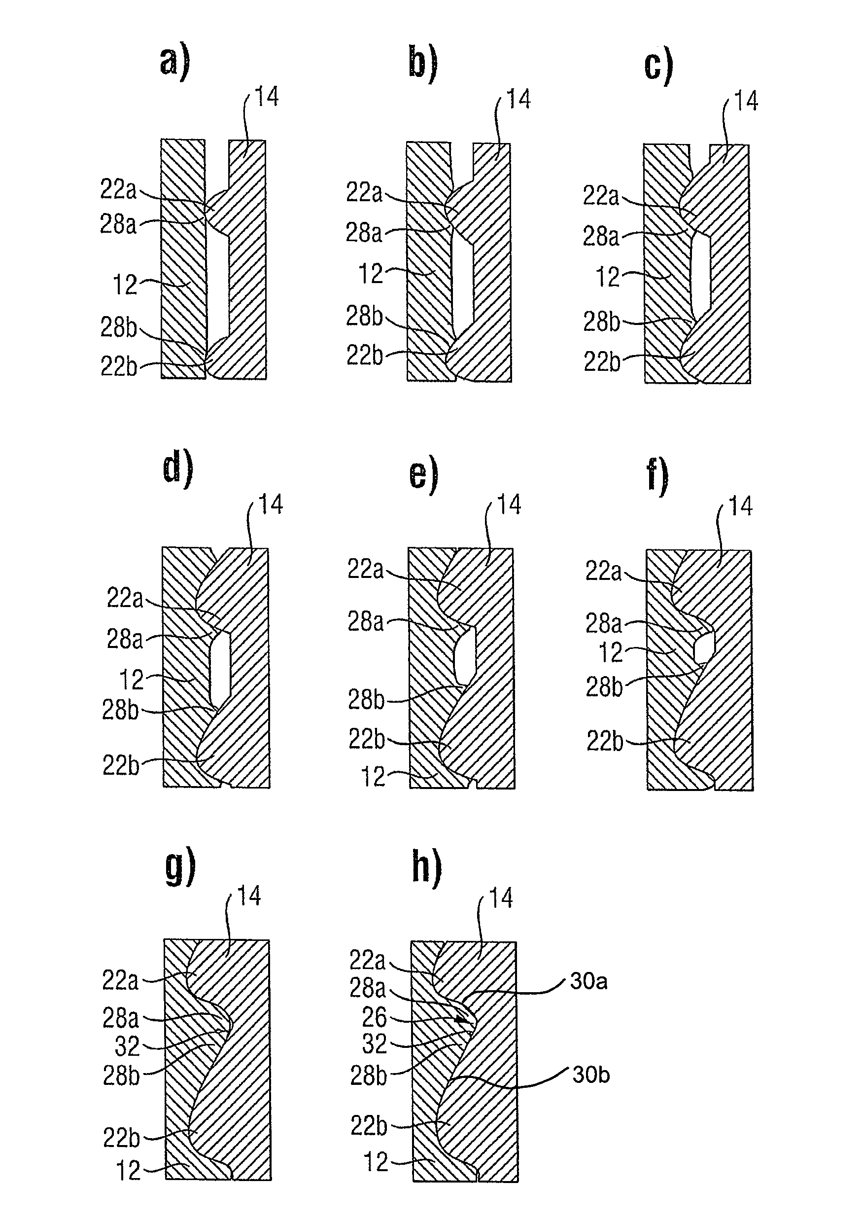
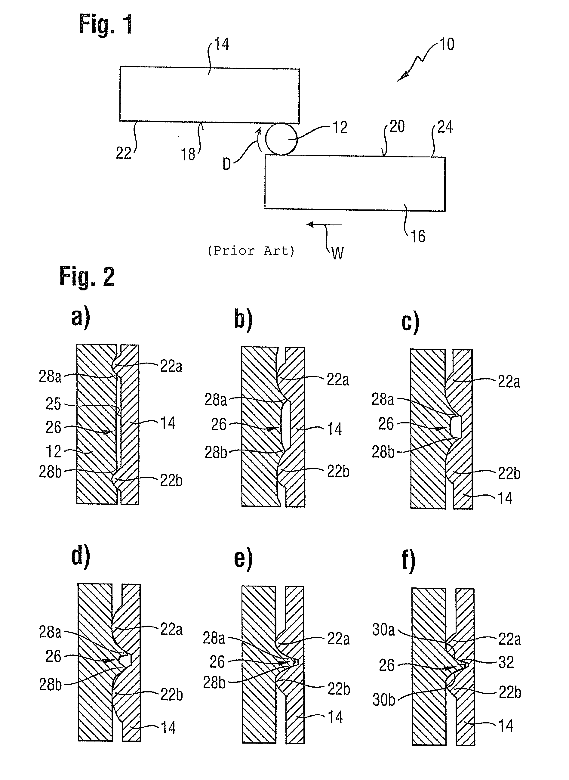
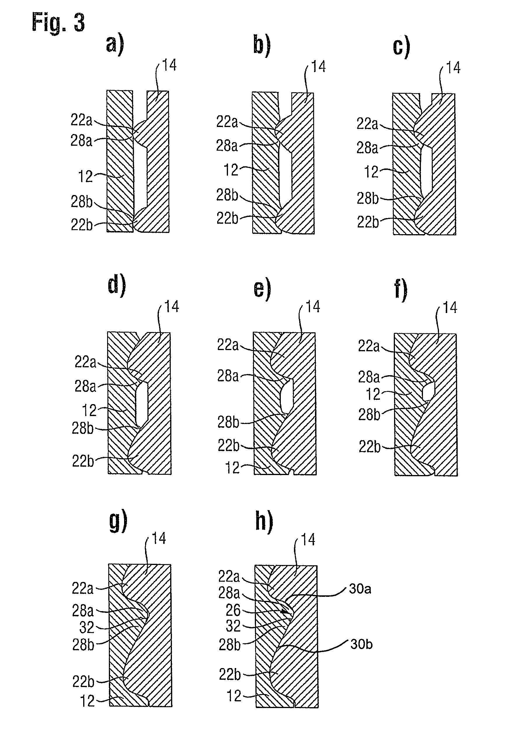
[0021]FIG. 1 schematically shows an arrangement 10 for rolling a thread of a screw in an essentially cylindrical screw blank 12. This arrangement consists essentially of two rolling dies 14, 16 that each have a rolling surface 18 and 20, respectively. The rolling surfaces 18, 20 are oriented parallel to each other and each have a profile 22 and 24, respectively. The first rolling die 14 is arranged so as to be stationary here, while the second rolling die 16 can be moved linearly parallel to its rolling surface 20 in a rolling direction W as well as parallel to the first rolling surface 18.

[0022]In order to form a thread, the blank 12 is positioned between the two rolling dies 14, 16, and the second rolling die 16 is subsequently moved in the rolling direction W. In this process, the blank 12 is rolled between the two rolling dies 14, 16 in a rotational direction D, whereby a thread is formed circumferentially in the blank 12 by several consecutive profiles 22, 24. For purposes of r...


PUM

PropertyMeasurementUnit
thread flank anglesaaaaaaaaaa
anglesaaaaaaaaaa

Abstract

In the case of a screw having at least one thread (26) that is formed by a rolling process, especially a flat-die rolling process, whereby the thread (26) consists of two ridges of material (28a, 28b) which are shaped from a blank (12) by means of cold-forming during the rolling process in such a way that the thread has a closing crease (32) where the ridges of material (28a, 28b) meet each other, it is provided that the closing crease (32) is situated in the area of a flank (30a, 30b) of the thread (26).

Description

[0001]This claims the benefit of German Patent Application DE 10 2011 078 256.7, filed Jun. 29, 2011 and hereby incorporated by reference herein.BACKGROUND[0002]The invention relates to a screw having at least one thread that is formed by means of a rolling process, especially a flat-die rolling process, whereby the thread consists of two ridges of material which are shaped from a blank by means of cold-forming during the rolling process in such a way that the thread has a closing crease where the ridges of material meet each other. The invention also relates to a method for forming a screw thread on the lateral surface of an essentially cylindrical blank so as to form at least one thread, by means of rolling, especially flat-die rolling.[0003]The invention especially relates to self-cutting screws.[0004]So-called flat-die rolling processes are known for purposes of forming threads on screws. In this process, an essentially cylindrical blank that is to be machined is positioned betw...

Claims


Application Information

Patent Timeline
Patent Type & Authority Patents(United States)
IPC IPC(8): E05B35/04
CPCF16B25/0026B21H3/06F16B25/0047
Inventor ROSENKRANZ, FALKACHLEITNER, CORINNA
Owner HILTI AG
Why Eureka
Try Eureka