Robotically mateable rotary joint electrical connector

a technology of electrical connectors and rotary joints, applied in the direction of coupling device connections, instruments, optical elements, etc., can solve the problems of not being suitable for general use, not many suitable for harsh or underwater environments, and not being able to rotate the keying

Inactive Publication Date: 2014-12-02
TELEDYNE INSTR INC
View PDF61 Cites 9 Cited by
  • Summary
  • Abstract
  • Description
  • Claims
  • Application Information

AI Technical Summary

Benefits of technology

[0017]The rear shell of the plug unit in one embodiment is free to rotate within the front shell via a slip-ring joint. The plug pin or contact module is held within the rear shell so as to rotate with the rear shell. Due to the design of the mating plug and receptacle contacts, the plug and receptacle modules can rotate relative to one another about the mating axis without degradation of the mating circuit's quality. In practice, the rear shell and plug module or pin rotate relative to the remainder of the connector to accommodate any torque or twist on the attached cable.
[0018]This connector includes mateable plug and receptacle contact modules that require no rotational keying. The arrangement includes a rotary joint to avoid or reduce the problem of jumper cable torque during mating, allowing the rear shell and plug pin to rotate relative to the front shell and receptacle unit, so that rotation of the connector on the cable's free end does not result in twisting of the jumper cable and the connector can be mated without imparting torque to the attached cable. Unlike other robotically mateable connectors, the cable exit in the connector is provided along the mating axis of the flying-lead plug.

Problems solved by technology

There are many known electrical rotary joint connectors which function in dry environments, but not many that are suitable for harsh or underwater environments.
Harsh environment rotary joint connectors are currently in use only for limited applications, such as down-hole drill strings, but they are not intended for general use, or for mating while completely submerged in a hostile environment.
The last of these, which requires rotational keying, is the most difficult to control.
All jumper cables have some resistance to torque, so that if one end is fixed, or substantially fixed due to great length, it is often very difficult to rotationally orient the free end into mating position, particularly if using the robotic manipulator of robot or robotic vehicle, such as an underwater vehicle or remotely operated vehicle (ROV).
The problem is increased for very short jumper cables which cannot support much twist.
Even in conditions where there is little cable torque, the problem of finding the mating key / key slot position increases the difficulty of connecting the jumpers.
Mating remotely is made more difficult and expensive by the requirement to control the rotational alignment of the individual components to be mated.
These connectors did solve the rotational alignment problem, but one problem with such connectors was that two contacts were not enough to satisfy the needs of most operations.
Another problem was that the receptacle's circular end-opening, which had to be pinched tightly closed before and after mating, had to be stretched several hundred percent to receive the plug's pin.
If mated for a long time, particularly at low ocean temperatures, the opening did not close upon de-mating, and the connector subsequently failed.
These connectors still have the rotational alignment problem, however, which somewhat limits their use, and requires special keying provisions for rotational alignment.
It proved to be too expensive and difficult to manufacture.
It also still had the problem of cross-connection during mating and de-mating as the plug's contacts wiped across receptacle contacts which were not their intended counterparts.
Underwater and other harsh environment connectors today typically require rotational alignment or keying for connection in a harsh environment, which makes robotic mating and demating difficult to accomplish, and also often results in torque or twisting of the flying lead jumper cables.

Method used


Image

  • Robotically mateable rotary joint electrical connector
  • Robotically mateable rotary joint electrical connector
  • Robotically mateable rotary joint electrical connector

Examples


Embodiment Construction

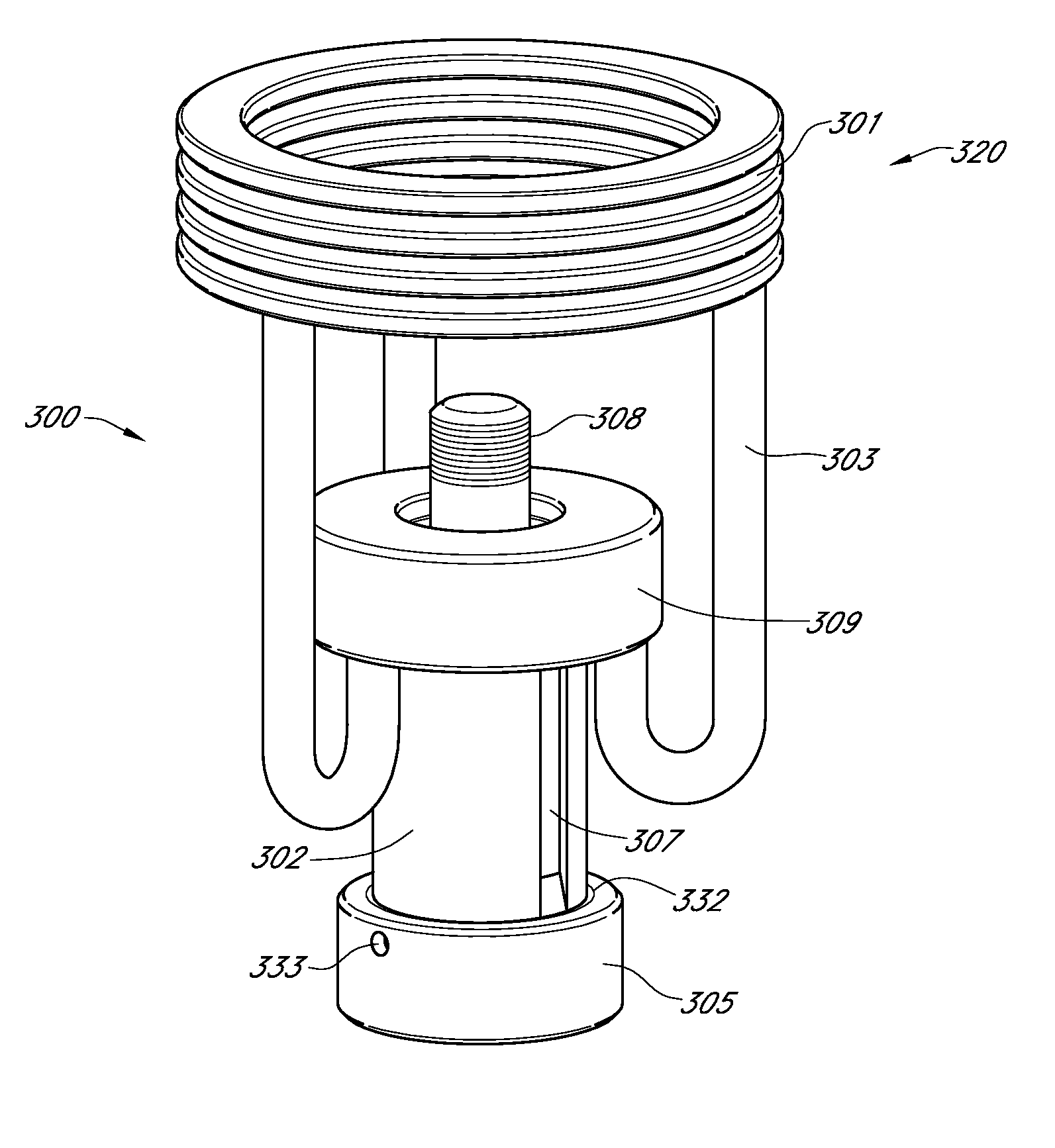
[0038]Certain embodiments as disclosed herein provide for a multi-circuit electrical connector having plug and receptacle units that can be mated and de-mated robotically without need to rotationally align the units.

[0039]After reading this description it will become apparent to one skilled in the art how to implement the invention in various alternative embodiments and alternative applications. However, although various embodiments of the present invention will be described herein, it is understood that these embodiments are presented by way of example only, and not limitation. As such, this detailed description of various alternative embodiments should not be construed to limit the scope or breadth of the present invention.

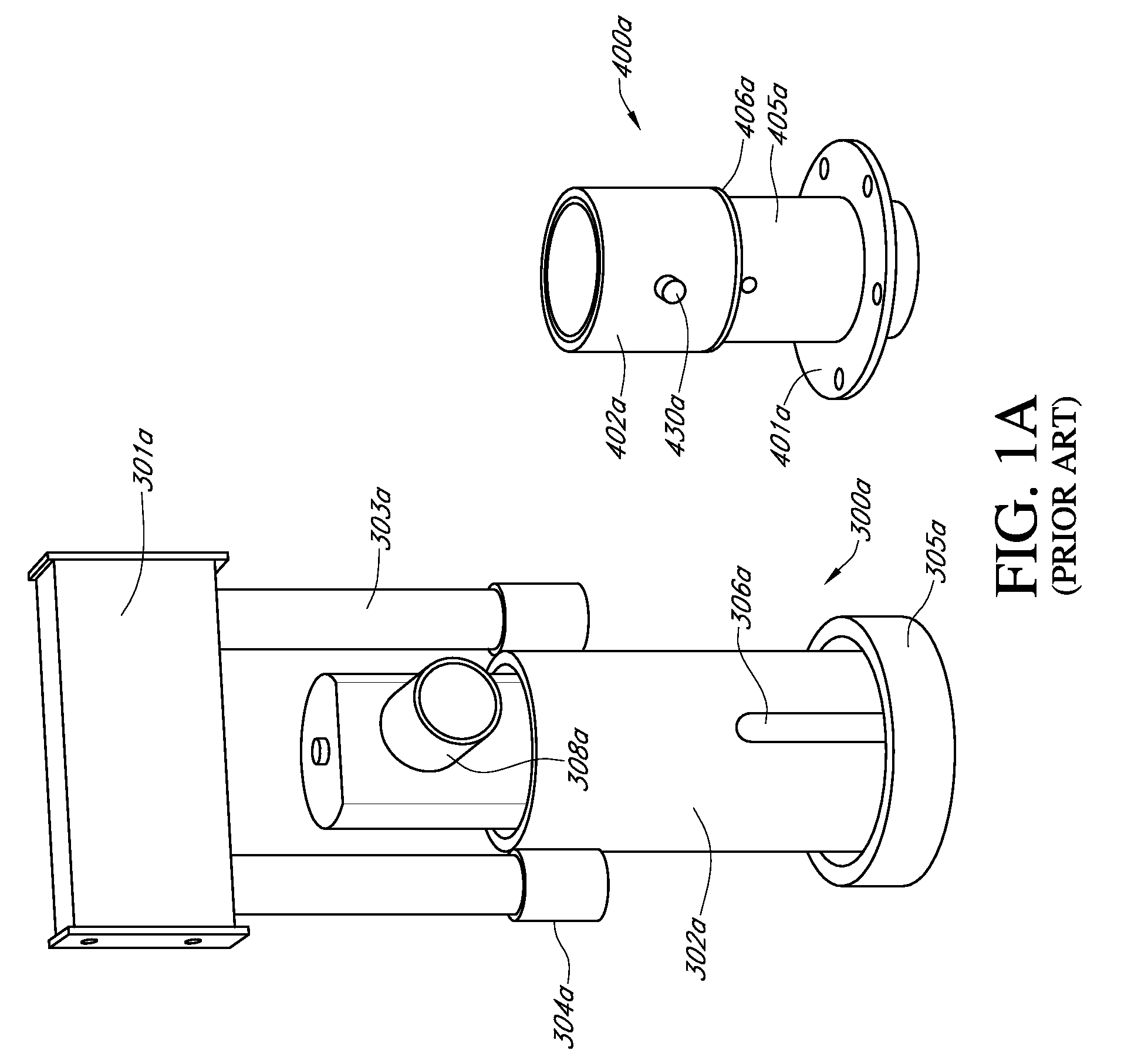
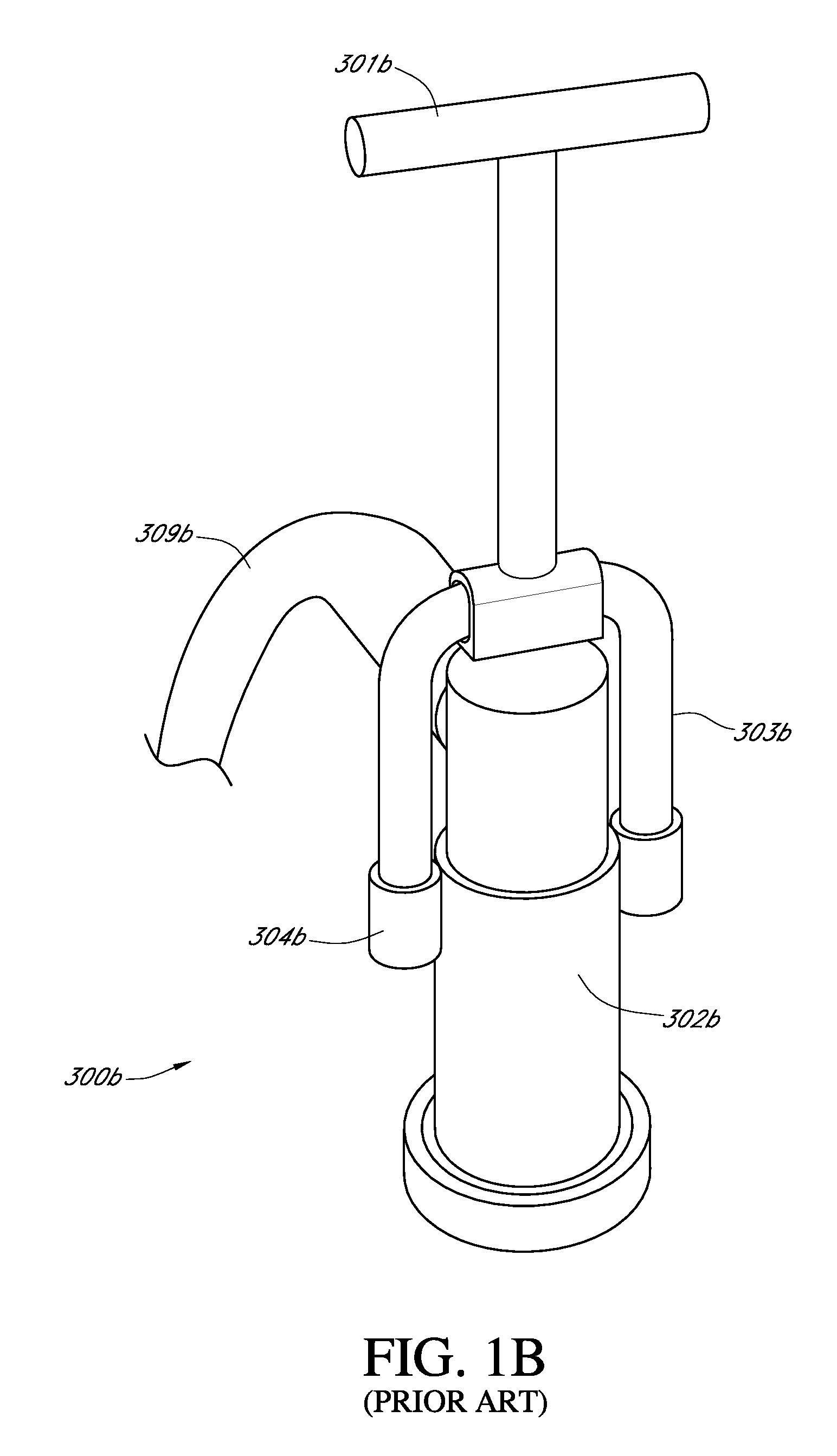
[0040]FIGS. 1A and 1B illustrate typical, existing connectors designed for underwater robotic mating and demating, for example by manned or ROV submersibles. The connectors each comprise one part intended to be sealably flange-mounted to an enclosed volume, such...


PUM


Abstract

A robotically mateable connector has a flying-lead plug unit and a receptacle unit adapted for releasable mating engagement with the plug unit. The plug unit includes a robotic manipulator grip assembly. A rear end shell which includes a cable attachment fitting holds a plug module having an outer surface carrying a plurality of axially spaced, annular contacts of gradually decreasing diameter towards a forward end of the module, and is rotatable relative to a plug front shell. The receptacle unit contains a receptacle module having a bore containing spaced annular contact seats of gradually increasing diameter designed for engagement with the plug contacts when the plug and receptacle units are fully mated. This provides a robotically actuated electrical connector that requires no rotational keying and relieves cable torque.

Description

RELATED APPLICATION[0001]The present application claims the benefit of U.S. provisional pat. App. Ser. No. 61 / 306,389, filed Feb. 19, 2010, the contents of which are incorporated herein by reference in their entirety.BACKGROUND[0002]1. Field of the Invention[0003]The present invention relates generally to connectors which can be mated and unmated in very harsh environments, such as underwater, and is particularly concerned with a robotically mateable, rotary joint electrical connector usable in such environments.[0004]2. Related Art[0005]There are many known electrical rotary joint connectors which function in dry environments, but not many that are suitable for harsh or underwater environments. Harsh environment rotary joint connectors are currently in use only for limited applications, such as down-hole drill strings, but they are not intended for general use, or for mating while completely submerged in a hostile environment.[0006]Modern underwater systems, particularly sea floor ...

Claims


Application Information

Patent Timeline
Patent Type & Authority Patents(United States)
IPC IPC(8): G02B6/38H01R35/04H01R13/44H01R13/523G02B6/36
CPCG02B6/3817G02B6/3604H01R35/04H01R13/523
Inventor CAIRNS, JAMES L.
Owner TELEDYNE INSTR INC
Why Eureka
Try Eureka