

Microfluidic chamber device and fabrication
a microfluidic chamber and chamber technology, applied in the direction of positive displacement liquid engines, laboratory glassware, paper/cardboard containers, etc., can solve the problems of reducing the reagent volume limit of methods, affecting downstream analysis, and using time-consuming manual techniques that are susceptible to errors
- Summary
- Abstract
- Description
- Claims
- Application Information
AI Technical Summary
Benefits of technology
Problems solved by technology
Method used
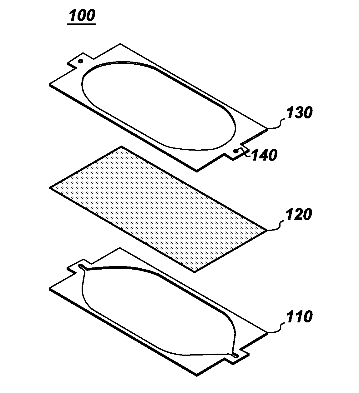
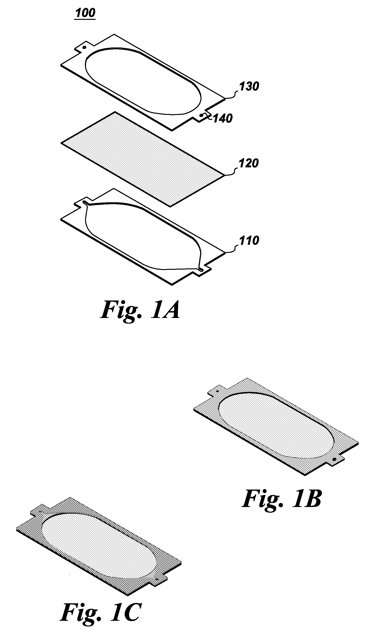
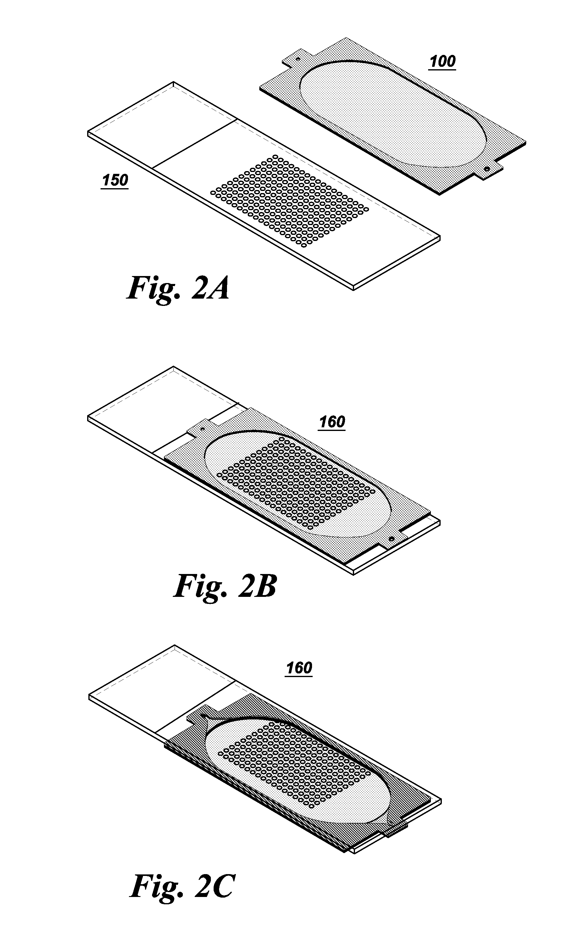
Image

Examples
Embodiment Construction
[0025]To more clearly and concisely describe and point out the subject matter of the claimed invention, the following definitions are provide for specific terms, which are used in the following description and the appended claims.
[0026]The singular forms “a”“an” and “the” include plural referents unless the context clearly dictates otherwise. Approximating language, as used herein throughout the specification and claims, may be applied to modify any quantitative representation that could permissibly vary without resulting in a change in the basic function to which it is related. Accordingly, a value modified by a term such as “about” is not to be limited to the precise value specified. Unless otherwise indicated, all numbers expressing quantities of ingredients, properties such as molecular weight, reaction conditions, so forth used in the specification and claims are to be understood as being modified in all instances by the term “about.” Accordingly, unless indicated to the contra...
PUM
| Property | Measurement | Unit |
|---|---|---|
| thickness | aaaaa | aaaaa |
| thickness | aaaaa | aaaaa |
| thickness | aaaaa | aaaaa |
Abstract
Description
Claims
Application Information