Magnet carrier for a pole housing

a technology of magnet carrier and pole housing, which is applied in the direction of magnetic circuit rotating parts, dynamo-electric machines, and shape/form/construction of magnetic circuits, etc. it can solve the problems of inconvenient use, time-consuming and costly methods, and inability to realize magnet gaps of less than 5 to 6 mm, so as to reduce the cost of components and low the level of investment in fitting devices, the effect of small magnet gaps

Inactive Publication Date: 2014-12-02
ROBERT BOSCH GMBH
View PDF12 Cites 0 Cited by
  • Summary
  • Abstract
  • Description
  • Claims
  • Application Information

AI Technical Summary

Benefits of technology

[0004]The object of the invention is to fit a magnet using low-cost components and with a low level of investment in fitting devices while maintaining extremely small magnet gaps.
[0006]One advantage of the magnet carrier according to the invention is that the positioning element and the securing element can be produced in a cost-effective manner. Furthermore, the positioning element and the securing element can be assembled in a simple manner, and therefore material costs can be saved even in the case of relatively low numbers of units.
[0009]According to a further embodiment of the invention, the positioning element is of V-shaped and elastic design. On account of the V shape of the positioning element, magnet gaps of different sizes can also be filled and uniform distribution of the magnets can be ensured. Furthermore, permanent pretensioning of the magnets over the service life of the product can be ensured.
[0010]In a further embodiment of the invention, the positioning element has lateral projections which each have an engagement element, wherein an elastic clip can be arranged as a securing element in and / or on the engagement element. The engagement element is preferably in the form of a latching lug and / or a stop. As a result, the securing element can be fixed both axially and also radially to the positioning element. On account of the latching lugs and / or stops, the positioning element and the securing element can securely and firmly hold the magnets even under high shaking loads.
[0011]According to a further embodiment of the invention, the positioning element has a central projection with an engagement element for attaching a speednut as the securing element. As a result, the securing element can be mounted and fixed on the positioning element in a simple manner.
[0012]In a further embodiment of the invention, the positioning element has a central projection with an insertion hole for fixing a shaft as the securing element. The securing element can be supplied tangentially by virtue of the insertion hole in the central projection, and therefore simple assembly can be ensured.

Problems solved by technology

However, magnet gaps of less than 5 to 6 mm cannot be realized with the leaf spring or else with the clip spring.
However, this method is time-consuming and costly since an adhesive bonding station is required for production.
This is not economical, primarily in the case of relatively low numbers of units.

Method used


Image

  • Magnet carrier for a pole housing
  • Magnet carrier for a pole housing
  • Magnet carrier for a pole housing

Examples


first embodiment

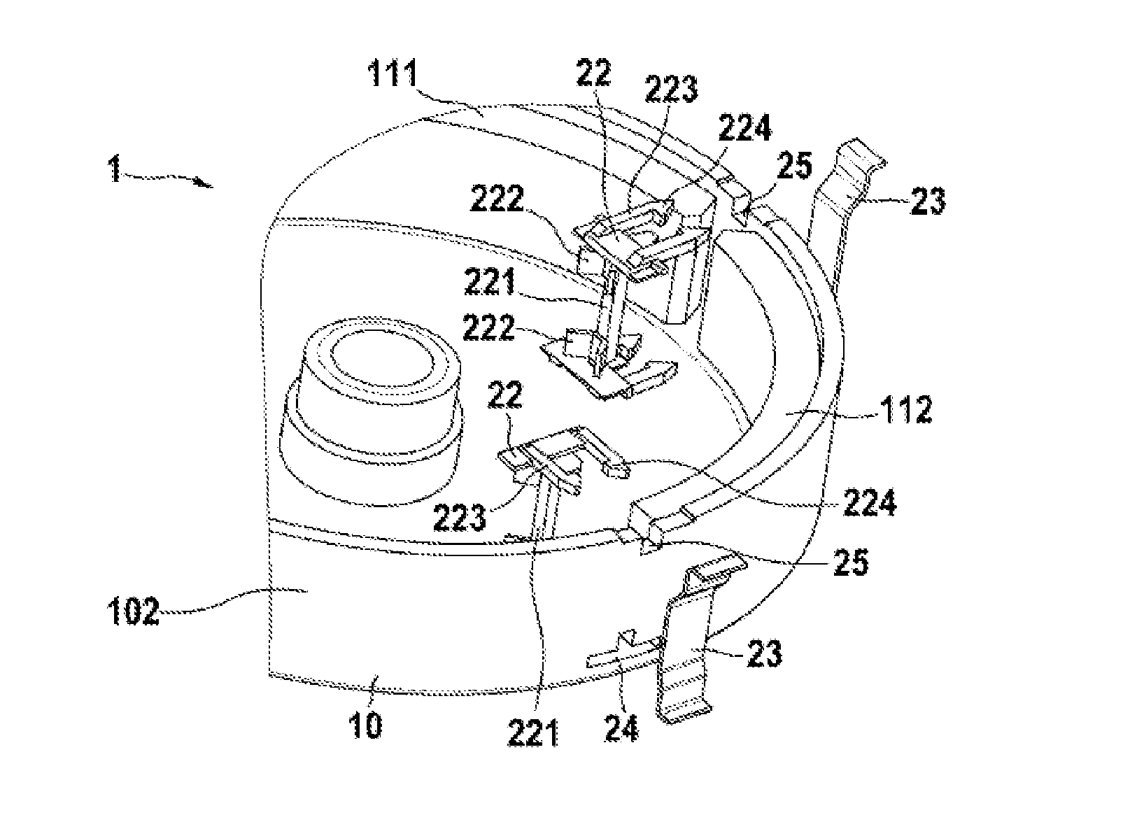
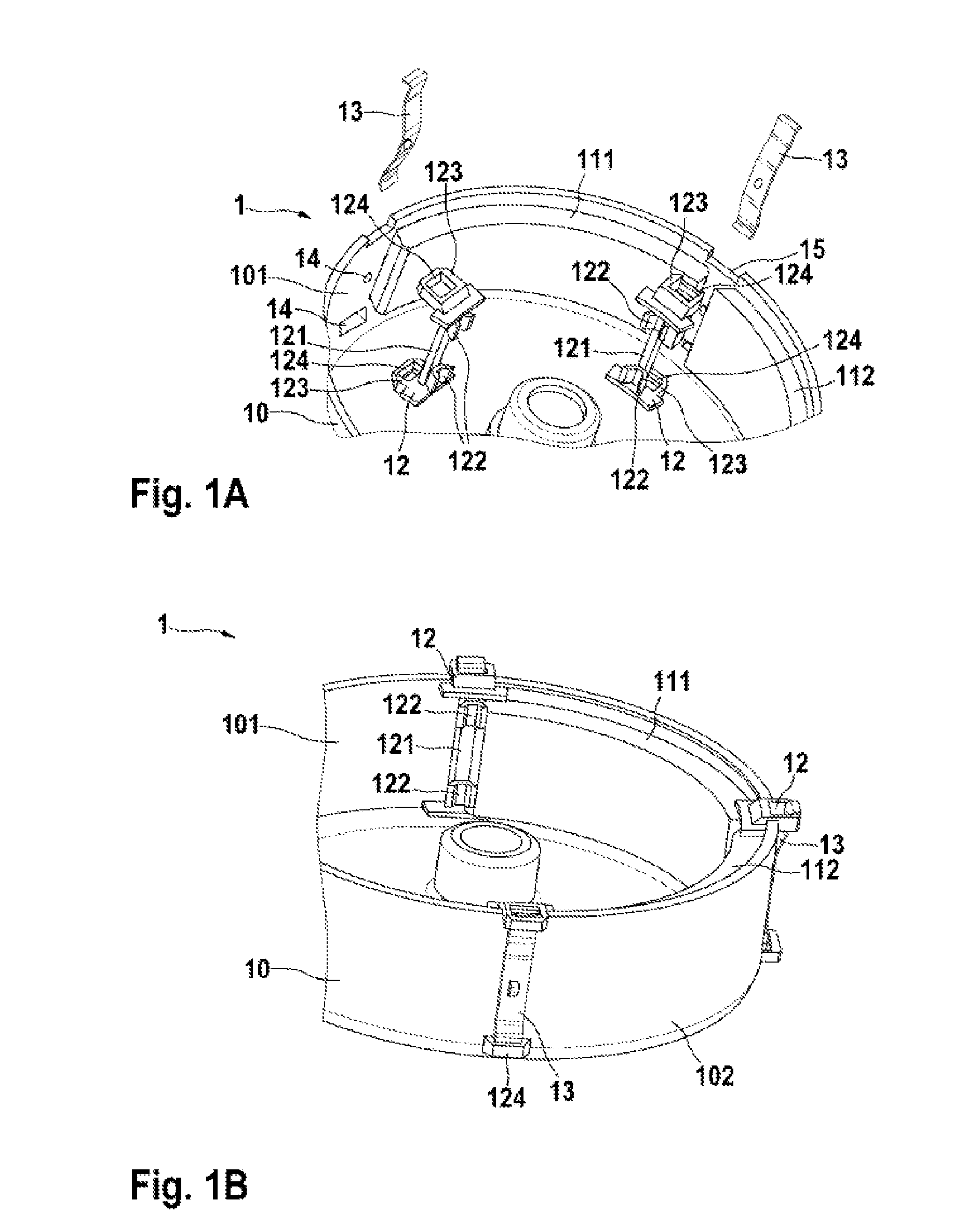
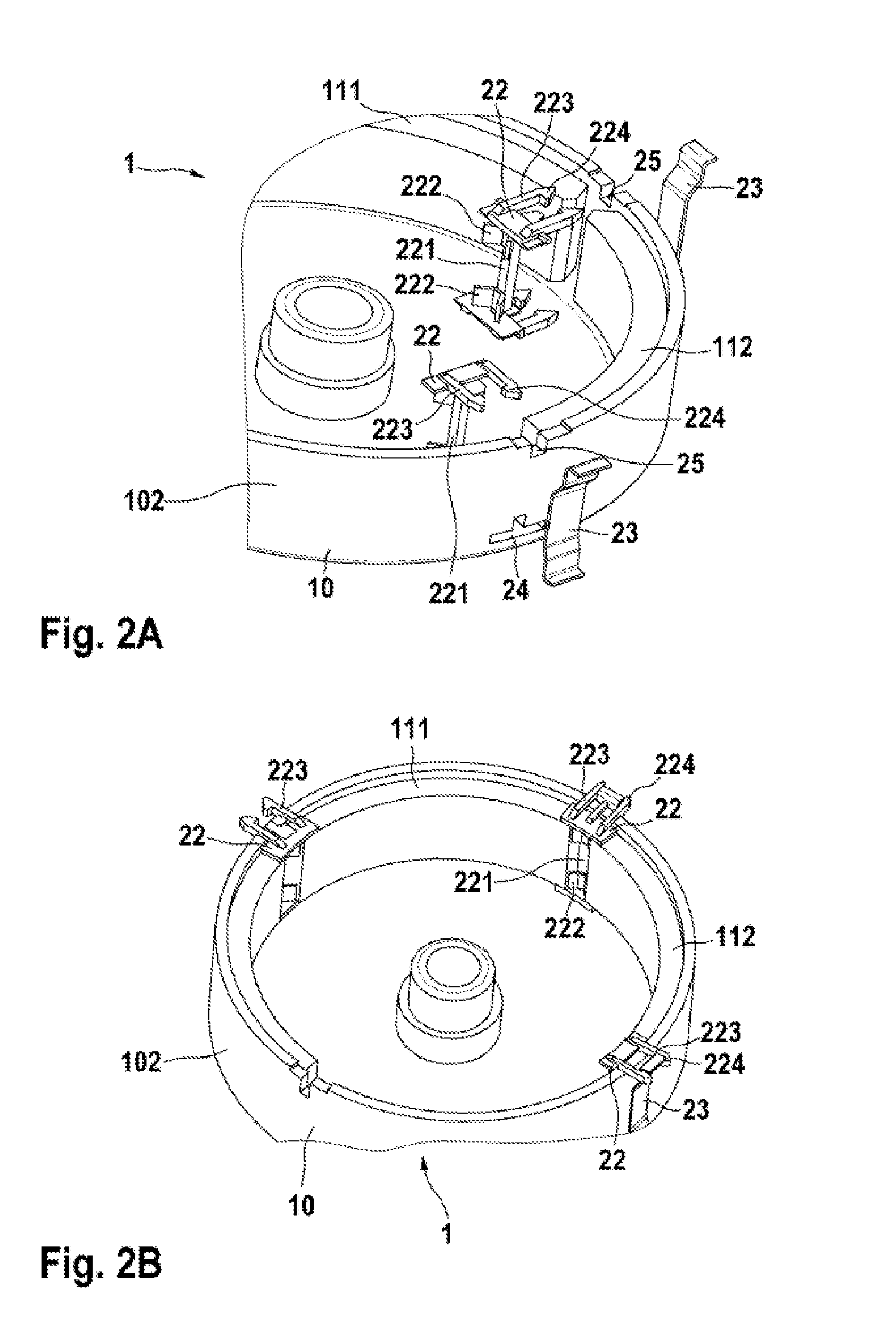
[0023]The positioning element 12, 22, 32, 42, 52 can be arranged on the pole housing wall 101. In this case, the positioning element 12, 22, 32, 42, 52 has a crosspiece 121, 221, 321, 421, 421, 521 with an attachment element 122, 222, 322, 422, 522 for fixing the at least two magnets 111, 112. The crosspiece 121, 221, 321, 421, 521 of the positioning element 12, 22, 32, 42, 52 can be designed in two ways. In a first embodiment, the crosspiece 121, 221, 321, 421 has at least two attachment elements 122, 222, 322, 422 which are arranged at the ends of the crosspiece 121, 221, 321, 421. In this case, the at least two attachment elements 122, 222, 322, 422 are of V-shaped design and have elastic properties. As a result, the magnets 111, 112 can be axially fixed in the pole housing 10. Furthermore, the magnets 111, 112 are pressed radially against the pole housing wall 101 by the V-shaped attachment elements 122, 222, 322, 422. The V-shaped design allows different magnet gaps to be fille...

second embodiment

[0024]In a second embodiment, the attachment element 522 is arranged along the entire crosspiece 521. In this case, the attachment element 522 is of V-shaped and elastic design in order to ensure pretensioning and uniform distribution of the magnets 111, 112. For the purpose of axial protection, a snap-action hook 56 engages around the pole housing 10 and latches into two outwardly projecting formations of the pole housing 10. The snap-action hook 56 is arranged between the attachment element 522 in this case. The snap-action hook 56 is of elastic design, like the attachment element 522, and therefore a contact pressure is exerted on the magnets 111, 112 via the attachment elements 520 of V-shaped design on the opposite pole housing wall 102. In order to compensate for the axial tolerance of the magnets 111, 112, the axial stops for the magnets 111, 112 are likewise of elastic design. For tangential tolerance compensation, that is to say to compensate for different gaps between the ...

third embodiment

[0028]FIG. 3A shows the magnet carrier 1 in a state in which it is not fitted and FIG. 2B shows said magnet carrier in a state in which it is fitted. The positioning element 32 has a central projection 323 with an engagement element 324 for attaching a speednut as the securing element 33. The central projection 323 on the positioning element 32 is of rectangular design in this case, and therefore the central projection 323 interacts with an opening 35 in the pole housing wall 101, 102. In this case, the positioning element 32 is routed through the opening 35 in the pole housing wall 101, 102 and attached to the speednut. In this case, the speednut has an oval shape. Lugs 34 are preferably provided in the center of the speednut in order to fix the speednut to the engagement element 324 in a simple and reliable manner.


PUM


Abstract

The invention relates to a magnet carrier (1) for a pole housing (10) for fastening magnets (111, 112) to a pole housing wall (101), wherein the magnet carrier (1) can be arranged between at least two magnets. The magnet carrier (1) comprises a positioning element (12, 22, 32, 42, 52) and a securing element (13, 23, 33, 43, 53). The positioning element (12, 22, 32, 42, 52) can be arranged on the pole housing wall (101). Furthermore, the positioning element (12, 22, 32, 42, 52) is designed to fix the at least two magnets (111, 112). The securing element (13, 23, 33, 43, 53) can be arranged on the pole housing wall (101) with the pole housing wall opposite of the positioning element (12, 22, 32, 42, 52). The securing element (13, 23, 33, 43, 53) is designed to be in engagement with the positioning element (12, 22, 32, 42, 52) and to thereby hold the positioning element (12, 22, 32, 42, 52) on the pole housing wall (101).

Description

BACKGROUND OF THE INVENTION[0001]The invention relates to a magnet carrier for a pole housing for attaching magnets to a pole housing wall, wherein the magnet carrier can be arranged between at least two magnets.[0002]A pole housing having a magnet carrier is preferably employed in a DC motor. In this case, a distinction is made between two- to four-pole DC motors and DC motors with four or more poles. In the case of two- to four-pole DC motors, the magnet gaps are generally so large that a leaf spring can be placed in the magnet gaps. As an alternative, a clip spring can also be used. The leaf spring is connected to the pole housing by means of solid or hollow rivets for attachment purposes. However, magnet gaps of less than 5 to 6 mm cannot be realized with the leaf spring or else with the clip spring.[0003]In the case of DC motors with four or more poles, a gap which is as small as possible is formed between the magnets for the purpose of optimizing the degree of efficiency, wher...

Claims


Application Information

Patent Timeline
Patent Type & Authority Patents(United States)
IPC IPC(8): H02K1/28H02K21/28H02K1/17H02K1/18
CPCH02K1/17
Inventor BITZER, HAROLD
Owner ROBERT BOSCH GMBH
Why Eureka
Try Eureka