Magnet carrier for a pole housing
a technology of magnet carrier and pole housing, which is applied in the direction of dynamo-electric machines, electrical apparatus, magnetic circuit shapes/forms/construction, etc., can solve the problems of inconvenient operation, time-consuming and costly methods, and inability to realize magnet gaps of less than 5 to 6 mm, so as to reduce the cost of components and low the level of investment in fitting devices, the effect of small magnet gaps
- Summary
- Abstract
- Description
- Claims
- Application Information
AI Technical Summary
Benefits of technology
Problems solved by technology
Method used
Image
Examples
first embodiment
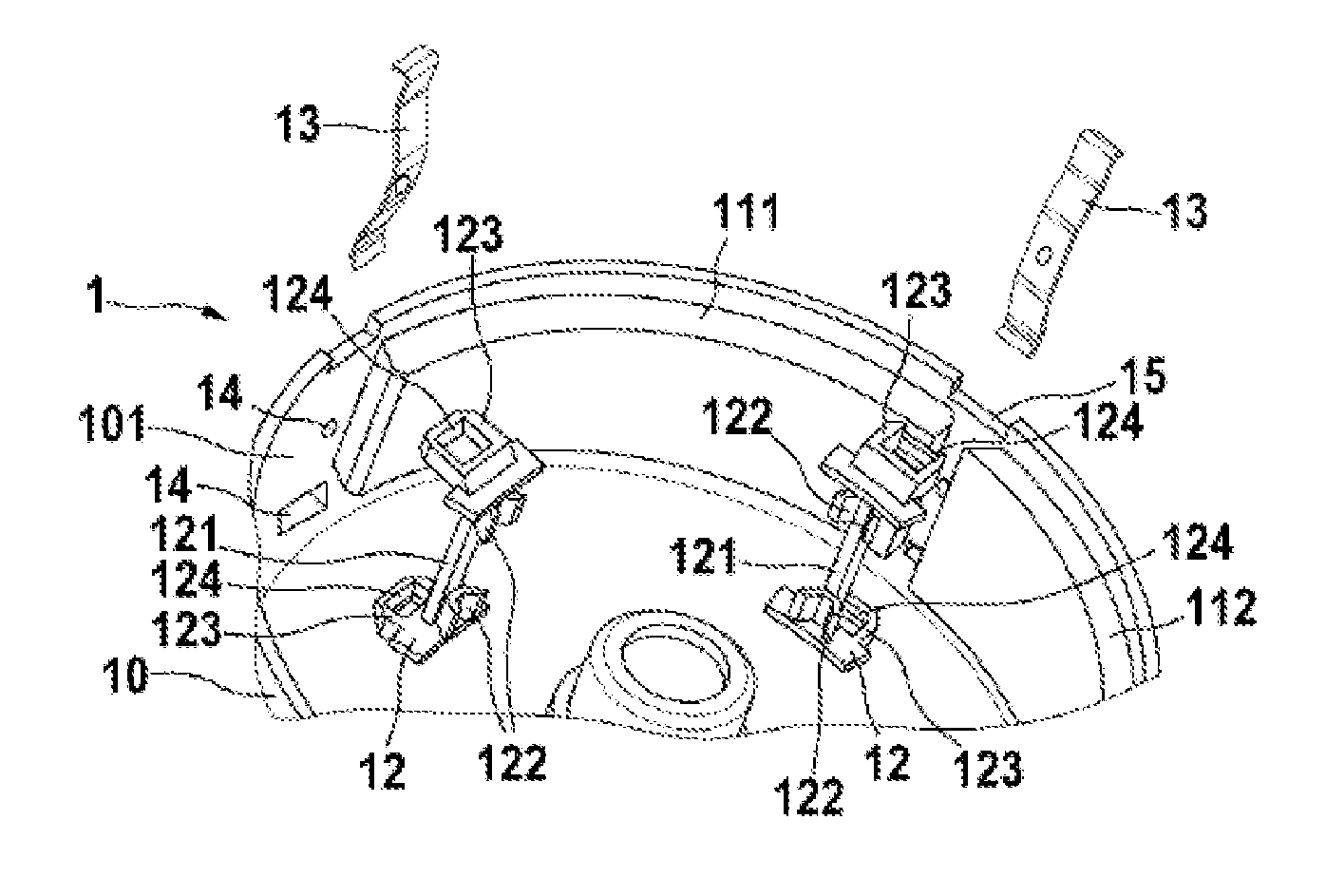
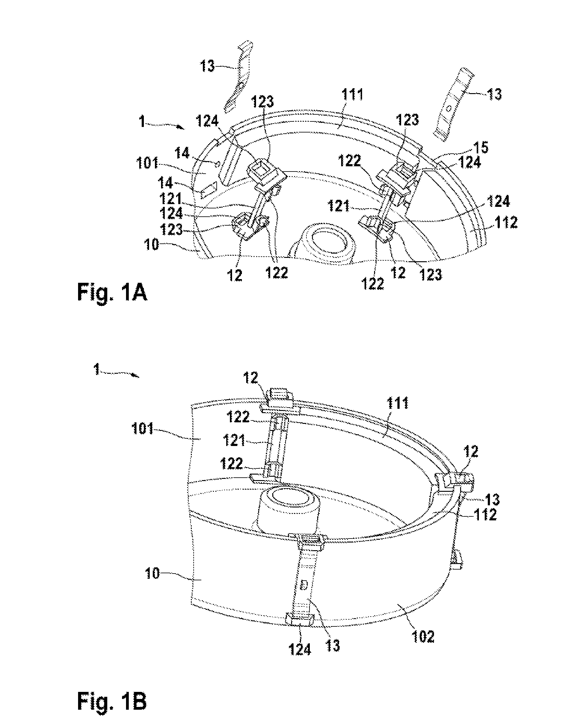
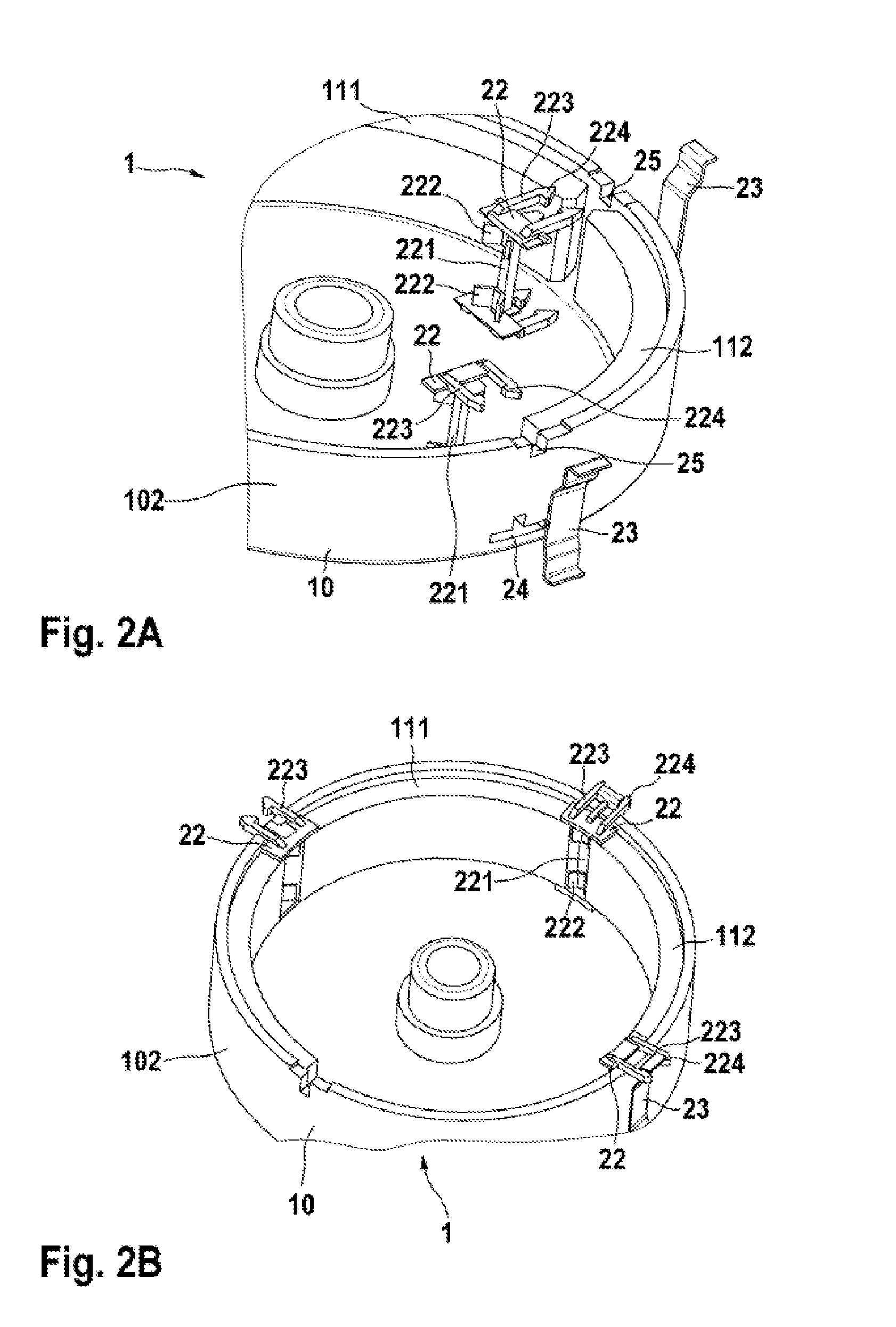
[0023]The positioning element 12, 22, 32, 42, 52 can be arranged on the pole housing wall 101. In this case, the positioning element 12, 22, 32, 42, 52 has a crosspiece 121, 221, 321, 421, 421, 521 with an attachment element 122, 222, 322, 422, 522 for fixing the at least two magnets 111, 112. The crosspiece 121, 221, 321, 421, 521 of the positioning element 12, 22, 32, 42, 52 can be designed in two ways. In a first embodiment, the crosspiece 121, 221, 321, 421 has at least two attachment elements 122, 222, 322, 422 which are arranged at the ends of the crosspiece 121, 221, 321, 421. In this case, the at least two attachment elements 122, 222, 322, 422 are of V-shaped design and have elastic properties. As a result, the magnets 111, 112 can be axially fixed in the pole housing 10. Furthermore, the magnets 111, 112 are pressed radially against the pole housing wall 101 by the V-shaped attachment elements 122, 222, 322, 422. The V-shaped design allows different magnet gaps to be fille...
second embodiment
[0024]In a second embodiment, the attachment element 522 is arranged along the entire crosspiece 521. In this case, the attachment element 522 is of V-shaped and elastic design in order to ensure pretensioning and uniform distribution of the magnets 111, 112. For the purpose of axial protection, a snap-action hook 56 engages around the pole housing 10 and latches into two outwardly projecting formations of the pole housing 10. The snap-action hook 56 is arranged between the attachment element 522 in this case. The snap-action hook 56 is of elastic design, like the attachment element 522, and therefore a contact pressure is exerted on the magnets 111, 112 via the attachment elements 520 of V-shaped design on the opposite pole housing wall 102. In order to compensate for the axial tolerance of the magnets 111, 112, the axial stops for the magnets 111, 112 are likewise of elastic design. For tangential tolerance compensation, that is to say to compensate for different gaps between the ...
third embodiment
[0028]FIG. 3A shows the magnet carrier 1 in a state in which it is not fitted and FIG. 2B shows said magnet carrier in a state in which it is fitted. The positioning element 32 has a central projection 323 with an engagement element 324 for attaching a speednut as the securing element 33. The central projection 323 on the positioning element 32 is of rectangular design in this case, and therefore the central projection 323 interacts with an opening 35 in the pole housing wall 101, 102. In this case, the positioning element 32 is routed through the opening 35 in the pole housing wall 101, 102 and attached to the speednut. In this case, the speednut has an oval shape. Lugs 34 are preferably provided in the center of the speednut in order to fix the speednut to the engagement element 324 in a simple and reliable manner.
PUM
 Abstract
Description
Claims
Application Information
 - R&D
- Intellectual Property
- Life Sciences
- Materials
- Tech Scout
- Unparalleled Data Quality
- Higher Quality Content
- 60% Fewer Hallucinations
Browse by: Latest US Patents, China's latest patents, Technical Efficacy Thesaurus, Application Domain, Technology Topic, Popular Technical Reports.
© 2025 PatSnap. All rights reserved.Legal|Privacy policy|Modern Slavery Act Transparency Statement|Sitemap|About US| Contact US: help@patsnap.com


