In-ear device with selectable frequency response

a frequency response and in-ear technology, applied in the field ofinear devices, can solve the problems of foam ear plugs, loss of hearing, hearing impairment, etc., and achieve the effect of easy adjustmen

Inactive Publication Date: 2014-12-02
SONOMAX TECH INC
View PDF11 Cites 8 Cited by
  • Summary
  • Abstract
  • Description
  • Claims
  • Application Information

AI Technical Summary

Benefits of technology

[0008]An advantage of the present invention is to provide an in-ear device that can be selectively adjusted for filtering a specific range or level of sound frequencies.
[0009]A further advantage of the present invention is to provide an in-ear device that will allow the wearer to select the degree of attenuation or frequency range protection according to the acoustic conditions of the environment, via a rotating button, a push toggle button or the like, or even a combination thereof.
[0010]Another advantage of the invention is to provide an in-ear device that can easily be adjusted without removing the same from the wearer's ear.
[0011]Yet another advantage of the invention is to provide an in-ear device that can be adjusted in such a way that it helps to keep the device in the wearer's ear, by applying positive pressure thereon, and optionally with a rotational motion towards natural insertion of the device inside the wearer's ear, especially when the protrusion is pre-shaped to fit the ear canal.
[0012]According to an aspect of the present invention, there is provided an in-ear device for selectively adjusting the range or level of sound frequencies reaching the inner ear of a wearer's ear, therefore having a selectable frequency response, said device comprising a main body having an innermost face and an outermost face, a canal inside the main body and extending from an inner end of the innermost face to an outer end of the outermost face of the main body and splitting into at least two derivative canals adjacent the outermost face within a generally annular zone defined thereon, each said canals being at least partially filled with a respective filling material, a knob, preferably rotatably attached to the outermost face of the main body and defining a peripheral edge thereof extending beyond the inner zone so as to cover the inner zone, said knob having a channel formed within an inner surface thereof, said channel extending generally radially from the knob periphery to an inner end thereof adjacent the annular zone whereby the channel being selectively in fluid communication with a respective said derivative canal upon rotation thereof.
[0013]Conveniently, the knob rotates about a knob axis generally coaxial with an axis of the annular zone.

Problems solved by technology

High-level sounds, and particularly the recurrence thereof, are known to cause hearing impairment, and in extreme cases, the loss of hearing.
One of the limitations of foam earplugs is that they are intended to filter a broad range of sound frequencies.
This procedure represents a disadvantage, since it renders the user unprotected during the transition.

Method used


Image

  • In-ear device with selectable frequency response
  • In-ear device with selectable frequency response
  • In-ear device with selectable frequency response

Examples


Embodiment Construction

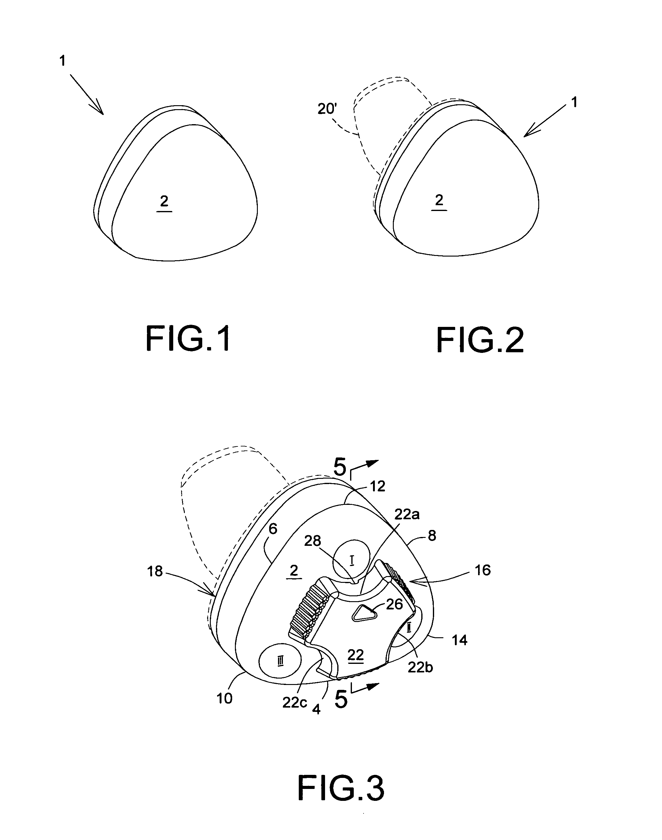
[0029]In FIGS. 1 and 2 there is depicted the device 1 of the invention comprising a main body 2. In general, the main body 2 can be designed and shaped so as to be safely placed in the outer ear of a specific wearer's ear. In FIGS. 1 and 2 are depicted two possible embodiments for the main body 2 according to the present invention. FIG. 1 represents the more general shape of main body 2; FIG. 2 represents an embodiment including a protrusion 20′ intended to be inserted inside of a wearer's ear canal.

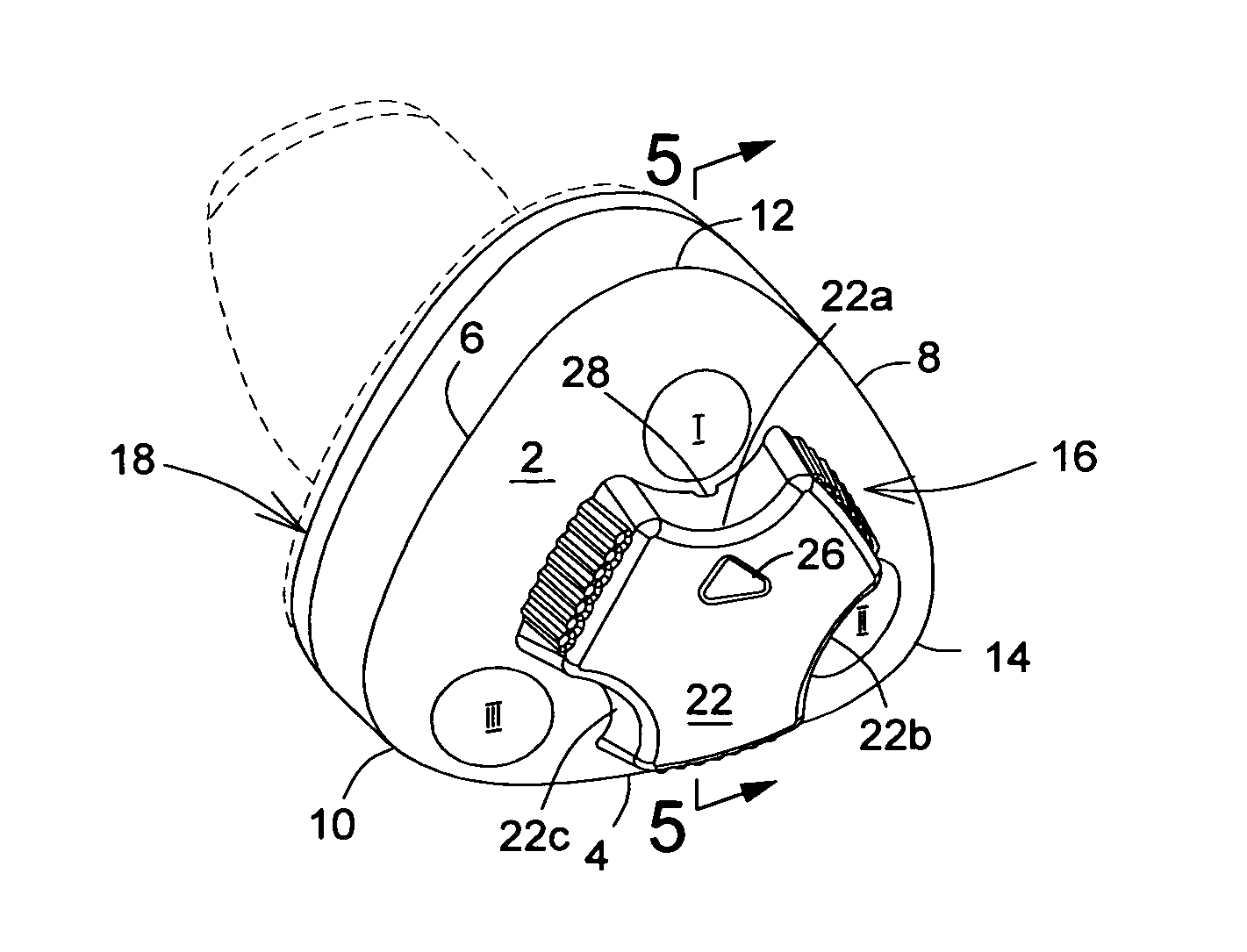
[0030]Referring to FIG. 3, there is shown a specific embodiment of the invention comprising a main body 2 having three sides 4, 6 and 8. The sides of the main body 2 are generally equal to one another, forming a main body 2 quasi-triangular in shape. By way of example, and not a limitation, the three sides 4, 6 and 8 of the main body 2 are convex; however, they might be shaped to resemble other geometrical forms. The device 1 might have at least three sides provided that at least two of ...


PUM


Abstract

An in-ear device comprises a main body for placement in the outer ear of a wearer and has at least two derivative canals each containing a filtering medium differing from one another in terms of their frequency suppression capabilities, and a preferably rotatable knob enabling selection of the respective filtering canal without the need for removal of the device from the ear.

Description

CROSS REFERENCE TO RELATED APPLICATIONS[0001]Benefit of U.S. Provisional Application for Patent Ser. No. 61 / 282,176 filed on Dec. 24, 2009, which is incorporated herein by reference, is hereby claimed.FIELD OF THE INVENTION[0002]This invention relates to in-ear devices, such as intra-aural hearing protectors (earplugs), earphones, or hearing-aide devices, and more specifically to an in-ear device which has a selectable frequency response with pre-determined values, the selection being made with the device being properly positioned inside the wearer's ear.BACKGROUND OF THE INVENTION[0003]High-level sounds, and particularly the recurrence thereof, are known to cause hearing impairment, and in extreme cases, the loss of hearing. In order to avoid the hearing impairments, numerous types of hearing protectors for noise reduction has been proposed to be used in different fields and uses such as military, industrial applications and music.[0004]One of the most common hearing protectors is ...

Claims


Application Information

Patent Timeline
Patent Type & Authority Patents(United States)
IPC IPC(8): H04R25/00A61F11/06A61B7/02A61F11/08
CPCA61F2011/085A61F11/08A61F11/085
Inventor VOIX, JÉRÉMIELAPERLE, JEAN-NICOLAS
Owner SONOMAX TECH INC
Why Eureka
Try Eureka