
Ink tank and printer therewith

a technology applied in the field of ink tanks and printers, can solve the problems of printers not printing normally, ink may smudge everywhere, waste of ink, etc., and achieve the effect of preventing the flow velocity of ink

Inactive Publication Date: 2014-12-09
QISDA OPTRONICS (SUZHOU) CO LTD
View PDF6 Cites 0 Cited by
  • Summary
  • Abstract
  • Description
  • Claims
  • Application Information

AI Technical Summary

Benefits of technology

[0005]A purpose of the present invention is to provide an ink tank and a printer therewith capable of preventing ink inside the ink tank from splashing to a waterproof moisture-permeable assembly when the printer is not in printing operation or the ink tank is not installed in the printer, so as to solve the problem that the waterproof moisture-permeable assembly may easily be stuck.
[0016]The lid of the ink tank of the printer and the intake passage of the present invention are improved. The waterproof moisture-permeable assembly is disposed on the lid, and the intake passage can be closed as the ink tank is not installed in the printer. As the ink tank is at a free state, such as not being installed in the printer, the ink stored in the ink tank can not splash on the waterproof moisture-permeable assembly no matter how to put or crash the tank body, so as to prevent the waterproof moisture-permeable assembly form being stuck and to prevent the flowing velocity of the ink from deceasing due to a bump or a crash of the waterproof moisture-permeable assembly.

Problems solved by technology

It results in the waste of the ink, and the ink may smudge everywhere.
Therefore, the printer may not print normally, and a package for preventing the ink tank from being crashed is utilized with higher cost.

Method used


Image

  • Ink tank and printer therewith
  • Ink tank and printer therewith
  • Ink tank and printer therewith

Examples


Embodiment Construction

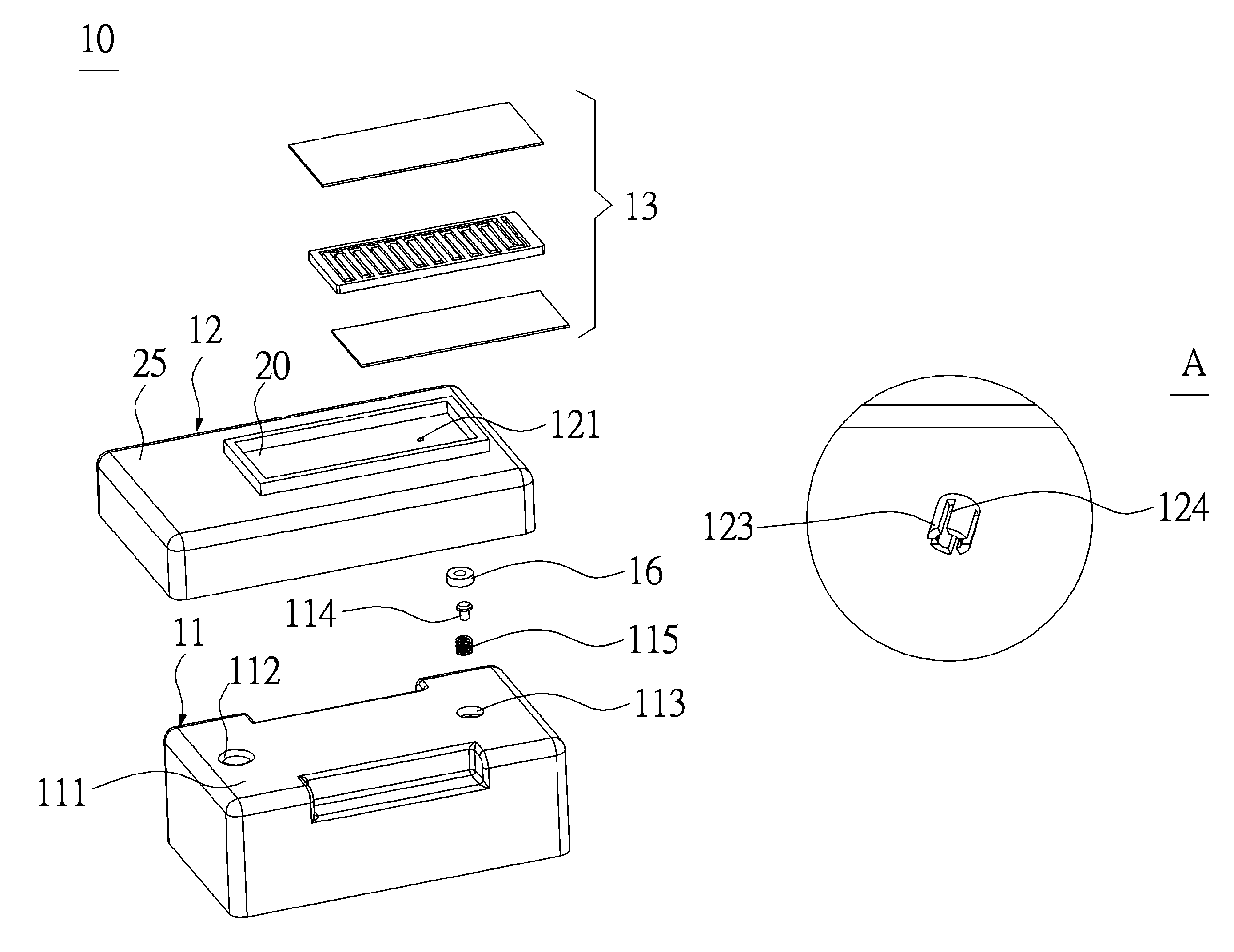
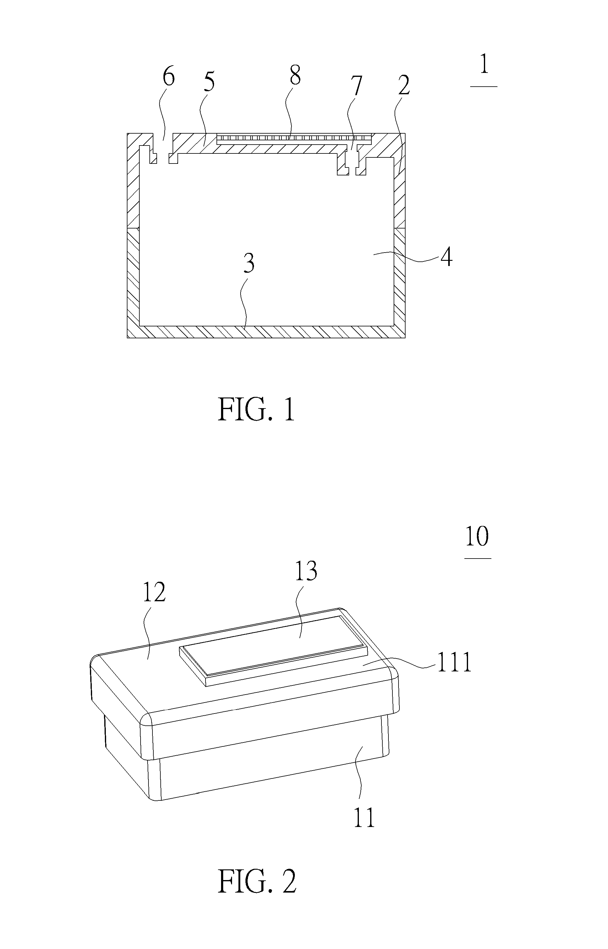
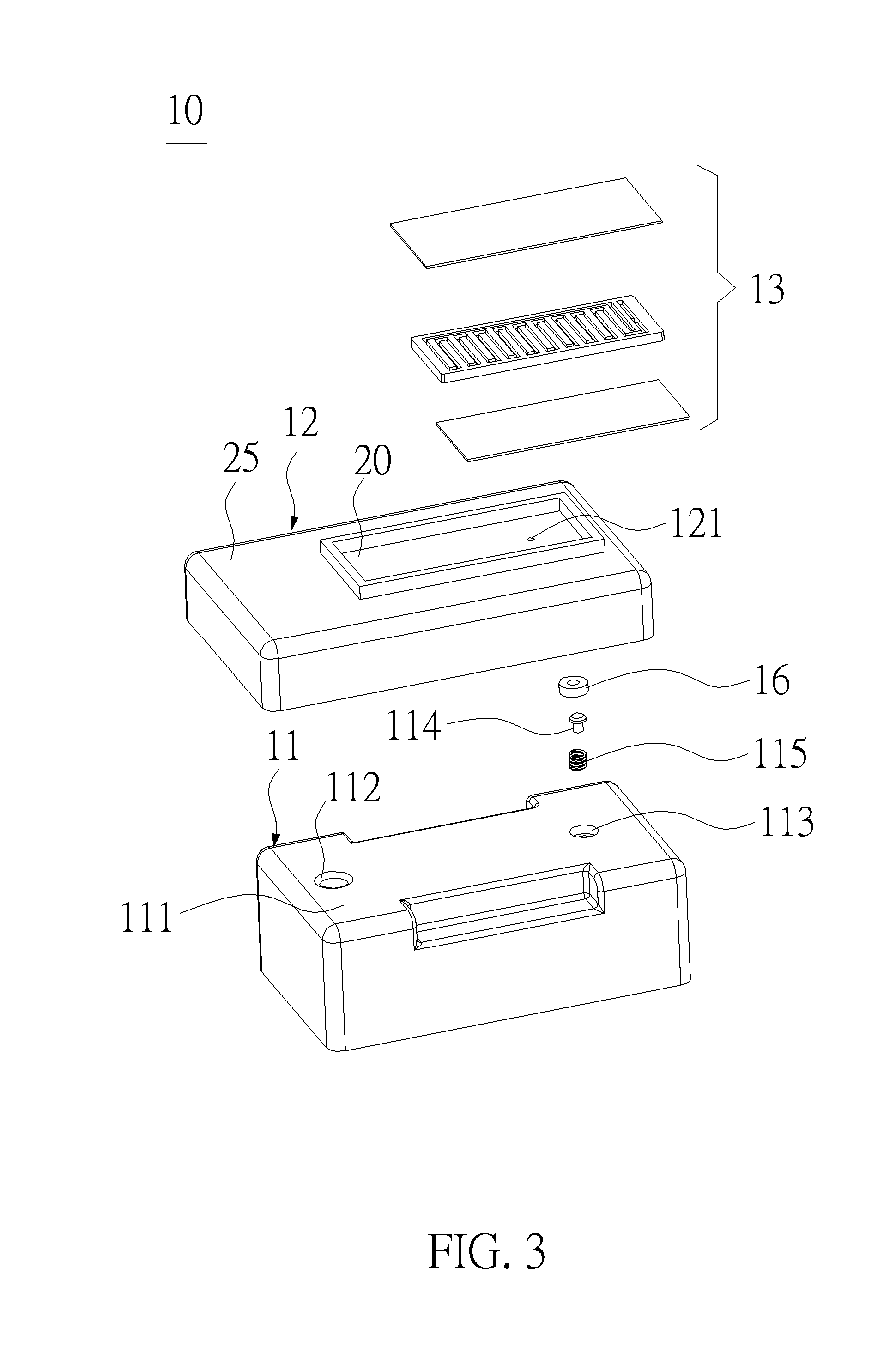
[0027]The present invention is to provide a printer, for example, an ink jet printer. The printer includes an ink tank 10. Please refer to FIG. 2 to FIG. 5. FIG. 2 is a diagram of the ink tank 10 according to an embodiment of the present invention. FIG. 3 is an exploded diagram of the ink tank 10 according to the embodiment of the present invention. FIG. 4 is a diagram of a lid 12 of the ink tank 10 at a different view angle according to the embodiment of the present invention. FIG. 5 is an enlarged diagram of area A shown in FIG. 4 according to the embodiment of the present invention. The ink tank 10 includes a tank body 11, a first pillar 114, a resilient component 115, a lid 12, a second pillar 123 and a waterproof moisture-permeable assembly 13. A chamber is formed inside the tank body 11 for containing ink, and an ink filling port 112 and a first opening 113 are formed on an upper side 111 of the tank body 11.

[0028]Generally, the tank body 11 includes an upper housing and a low...


PUM


Abstract

The present invention is to provide a printer and an ink tank therein. The ink tank includes a tank body, a first pillar, a resilient component, a lid, a second pillar and a waterproof moisture-permeable assembly. An ink filling port and a first opening are formed on an upper side of the tank body. The first pillar and the resilient component are disposed in the first opening and forming an openable intake passage cooperatively. The lid covers on the upper side of the tank body, a second opening and a second pillar are formed on the lid. The second pillar includes a communicating portion, and a waterproof moisture-permeable assembly is disposed on the lid and communicating with the communicating portion through the second opening. The present invention is to prevent the waterproof moisture-permeable assembly from being stuck by ink when the printer is not in printing operation.

Description

BACKGROUND OF THE INVENTION[0001]1. Field of the Invention[0002]The present invention relates to an ink tank and a printer therewith, especially to an ink tank and a printer therewith capable of preventing ink inside the ink tank from splashing to a waterproof moisture-permeable assembly when the printer is not in printing operation or the ink tank is not installed in the printer.[0003]2. Description of the Prior Art[0004]Please refer to FIG. 1. FIG. 1 is a partial structural diagram of a conventional ink tank in the prior art. The conventional ink tank of a printer includes an ink tank body 1, and the ink tank body 1 includes an upper housing 2 and a lower housing 3. Ink 4 is contained in a chamber enclosed by the upper housing 2 and the lower housing 3 cooperatively, and an ink filling port 6 and a breath port 7 are disposed on a top side 5 of the upper housing 2 . As the ink 4 is reducing, outside air passes through the breath port 7 and flows into the chamber so as to keep the i...

Claims


Application Information

Patent Timeline
Patent Type & Authority Patents(United States)
IPC IPC(8): B41J2/175
CPCB41J2/17513
Inventor QIAN, MING-KUANHU, ZHENGLONG
Owner QISDA OPTRONICS (SUZHOU) CO LTD
Learn More