Supercharge Your Innovation With Domain-Expert AI Agents!

Pedal device

a technology of pedals and supports, applied in the direction of mechanical control devices, process and machine control, instruments, etc., can solve the problems of increasing the deformation of the supporting plate, increasing the deformation of the accelerator pedal, and reducing the strength of the nail member including the supporting plate and the nail

Inactive Publication Date: 2014-12-16
HONDA MOTOR CO LTD +1
View PDF19 Cites 0 Cited by
  • Summary
  • Abstract
  • Description
  • Claims
  • Application Information

AI Technical Summary

Benefits of technology

The pedal device maintains strength and durability over years by distributing loads effectively through the higher-stiffness fitting nail and preventing the engagement nail from bending or coming off, thus preventing degradation and ensuring reliable operation.

Problems solved by technology

Also, because the nail is engaged with the stopper member by elastically deformed supporting plate, an amount of deformation of the supporting plate increases when the nail is large.
Therefore, there arises a problem that the accelerator pedal tends to be degraded over the years because the strength of the nail member including the supporting plate and the nail decreases.

Method used


Image

  • Pedal device
  • Pedal device
  • Pedal device

Examples


Embodiment Construction

[0031]Hereinafter, referring to FIGS. 1-7, embodiments of the present invention will be explained in detail.

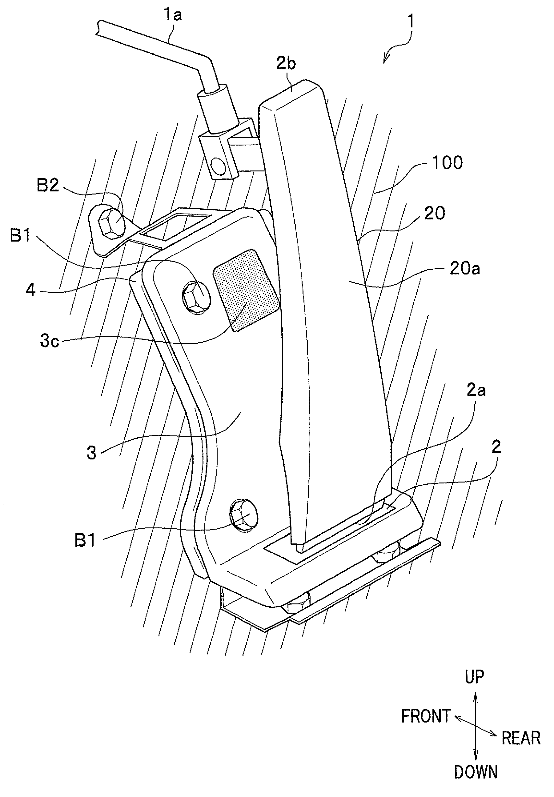
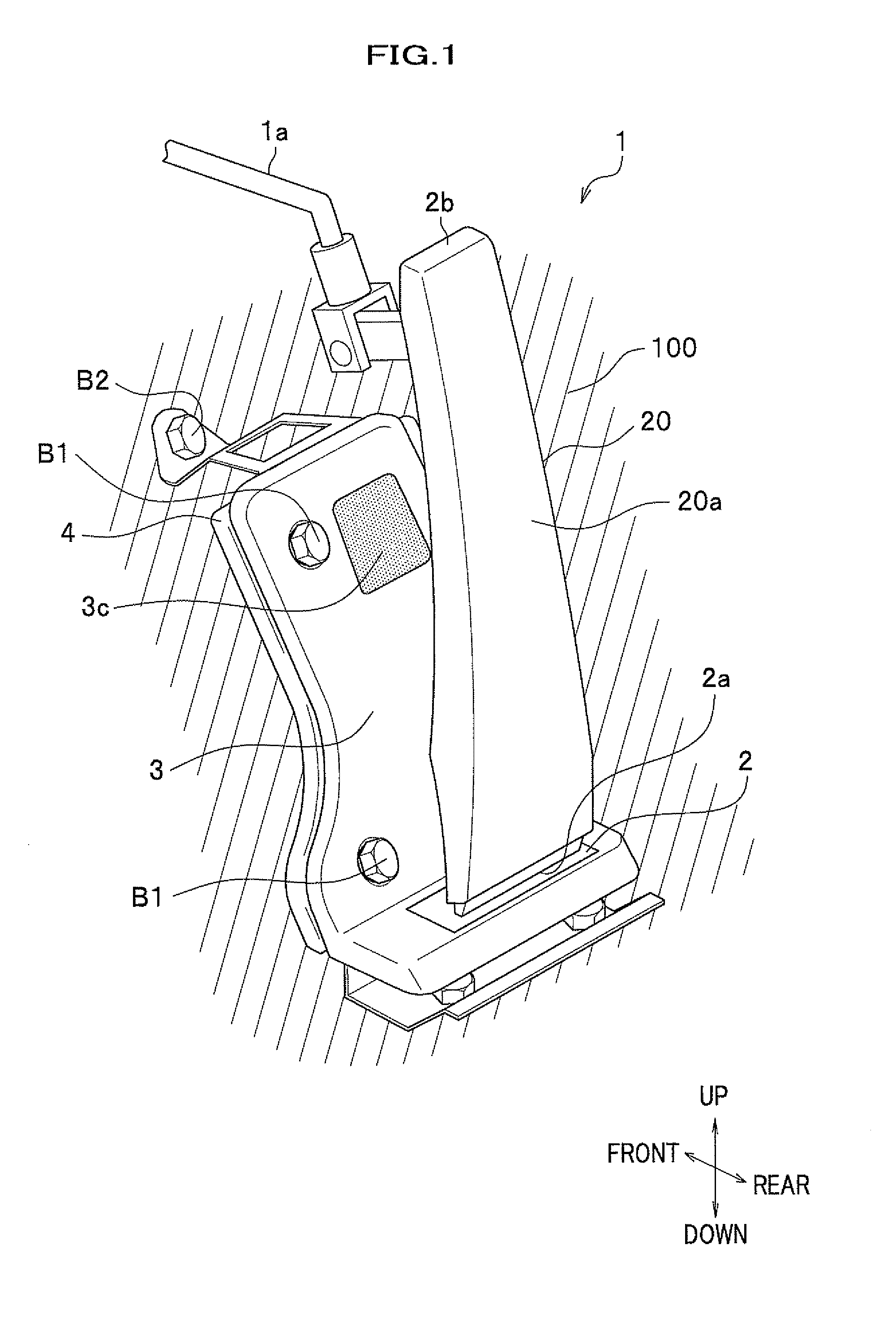
[0032]As shown in FIG. 1, for example, a pedal device 1 according to this embodiment is fixed to a floor 100 of a driver's seat in a vehicle as an accelerator pedal of the vehicle, and includes a pad member 2 including a pad 20 depressed by receiving depression force exerted by the driver; and a stopper bracket 3 used as a stopper member to fix the pad member 2 to the floor 100 via a mounting bracket 4. Although the mounting bracket 4 will be explained in detail later, for example, the mounting bracket 4 is fixed to the floor 100 by a bolt B2. The stopper bracket 3 is formed into a configuration which is along the floor 100. For example, when the floor 100 rises at front of the vehicle, the stopper bracket 3 may be formed to have an approximately L shaped cross section. The pad member 2 is fitted into the stopper bracket 3 via a structure described later, and the stopper brack...


PUM


Abstract

An object of the present invention is to provide a pedal device in which the pad member can be fixed to the stopper member easily at the time of mounting, and which does not tend to be degraded over the years. In order to achieve the above object, the present invention provides a pedal device including: a stopper member attached to a floor of a driver's seat of a vehicle; and a pad member which has a pad fitted into the stopper member and receives a depression force exerted by a driver.

Description

CROSS-REFERENCE TO RELATED APPLICATION[0001]The present application claims benefit of the filing date of Japanese Patent Application No. 2009-146734 filed on Jun. 19, 2009 which is incorporated herein by reference.BACKGROUND OF THE INVENTION[0002]1. Field of the Invention[0003]The present invention relates to a pedal device which is provided in a vehicle.[0004]2. Description of Related Art[0005]For example, a pedal (an organ pedal) whose fulcrum is on a floor side of a vehicle body may be used as an accelerator pedal of a vehicle. JP 2004-106776 A discloses an accelerator pedal in which a pad member is fixed to a stopper member by a snap-fit mechanism by which a nail member including a nail provided on a resinous pad member is engaged with the stopper member on a vehicle body side at the time of mounting.[0006]According to the technique disclosed in JP 2004-106776 A, the nail is engaged with the stopper member by the snap-fit mechanism which elastically deforms a supporting plate wh...

Claims


Application Information

Patent Timeline
Patent Type & Authority Patents(United States)
IPC IPC(8): G05G1/46G05G1/36G05G1/44
CPCG05G1/36G05G1/44G05G1/46Y10T74/20888Y10T74/20534
Inventor NEBUYA, HIDETOOKA, SHINJIEBARA, TORUKOBAYASHI, MASATOKATO, TERUO
Owner HONDA MOTOR CO LTD
Features
  • R&D
  • Intellectual Property
  • Life Sciences
  • Materials
  • Tech Scout
  • Unparalleled Data Quality
  • Higher Quality Content
  • 60% Fewer Hallucinations
Learn More