Nonlinear air stop valve structure

a technology of air stop valve and air column, which is applied in the direction of functional valve types, dolls, transportation and packaging, etc., can solve the problems of air in the air sealing body being discharged, the ability to lock air in the air column cannot be too long, and the buffering function of the air sealing body being lost, so as to reduce the backflow of air and achieve good buffering function of the air sealing body

Active Publication Date: 2014-12-16
AIR BAG PACKING
View PDF53 Cites 7 Cited by
  • Summary
  • Abstract
  • Description
  • Claims
  • Application Information

AI Technical Summary

Benefits of technology

[0010]Therefore, it is a primary objective of the present invention to overcome the drawbacks of the prior art by providing an air stop valve used in an air sealing body capable of reducing the backflow of air, since the air in the conventional air stop valve circulates and enters into the original path of the air columns and flows back into the atmosphere easily, so that it is difficult to maintain the sealed air for long, and the invention can maintain a good buffering function of the air sealing body for too long.
[0013]Therefore, when the air in the sealing body flows back along the inlet path of the air stop valve, the air is blocked and guided by the left and right arcs and divides the backflow of air, such that a very small quantity of air flowing back to the air inlet, so as to achieve the effect of preventing the backflow of air without causing difficulties or unsmooth operations, and the invention can maintain a good buffering condition of the air sealing body.
[0016]A flow guide passage is formed between the upper and lower arcs for guiding back flowing air, and a lower end of the arc is used as a natural block when the air flows back, so that the back flowing air is blocked by the lower end of the arc, and the flow guide passage guides the blocked air accordingly into a sealed space, and the blocking and air guiding effects of the left and right arcs prevent a gas or air stored in the sealing body from flowing back to the original air inlet and prevent a backflow, so that the sealing body can maintain a long air-lock time to assure a buffering capability of the sealing body. The flow guide passage has a hot-sealing length extended to a boundary of the sealed space, so that the sealed space is partitioned into a plurality of independent sealed chambers, and gas guided from the flow guide passage will not be overlapped or interfered with one another.
[0017]The inner membrane and a single outer membrane of the sealing body are hot sealed with the arc in advance to form a seal between the air stop valve and the outer membrane, and after the sealing body is inflated, there is no internal expansion, thus an internal pressure is produced to compress the air stop valve to define an air stop and improve an air stopping effect.
[0018]Alternatively, the air stop valve is installed independently between the outer membranes, and after the sealing body is inflated, an internal pressure of the sealing body increases due to the expansion of air, so that both sides of the air stop valve are pressed to form an air stop to improve an air stopping effect.
[0020]The sealing body comprises at least one air chamber formed therein and disposed between the outer membranes, and each air chamber comprises an air inlet, and the left and right arcs coupled to the air inlet and the air inlet hot sealing line of the heat resisting material are coupled closely with one another to prevent the air flowing back from a joint of the air inlet and the left and right arcs to an inflating channel of the sealing body to leak from the sealing body.

Problems solved by technology

However, the aforementioned structure also has a serious drawback, since the one-way air stop valve can lock air, but the capability of locking air in the air columns of the air sealing body cannot last too long.
In other words, such one-way air stop valve is unable to block and prevent air in the air column from circulating and entering into the original path of the air columns and flowing back into the atmosphere, so that the air in the air columns of the air sealing body will flow to the outside slowly and unconsciously.
As a result, the air in the air sealing body will be discharged to lose the buffering function.
However, the structure adopts a linear blocking and a turning which violates the theory of fluid dynamics.
As a result, the inflation operation will be very unsmooth.
4. In Pat. Pub. No. US 2007 / 0267094 A1, an air stop valve structure having a wide inlet, a narrow middle section and an even wider air outlet, but this structure still adopts the concept of the linear path, and fails to avoid the problem of air flowing along the linear path back to the outside.

Method used


Image

  • Nonlinear air stop valve structure
  • Nonlinear air stop valve structure
  • Nonlinear air stop valve structure

Examples


Embodiment Construction

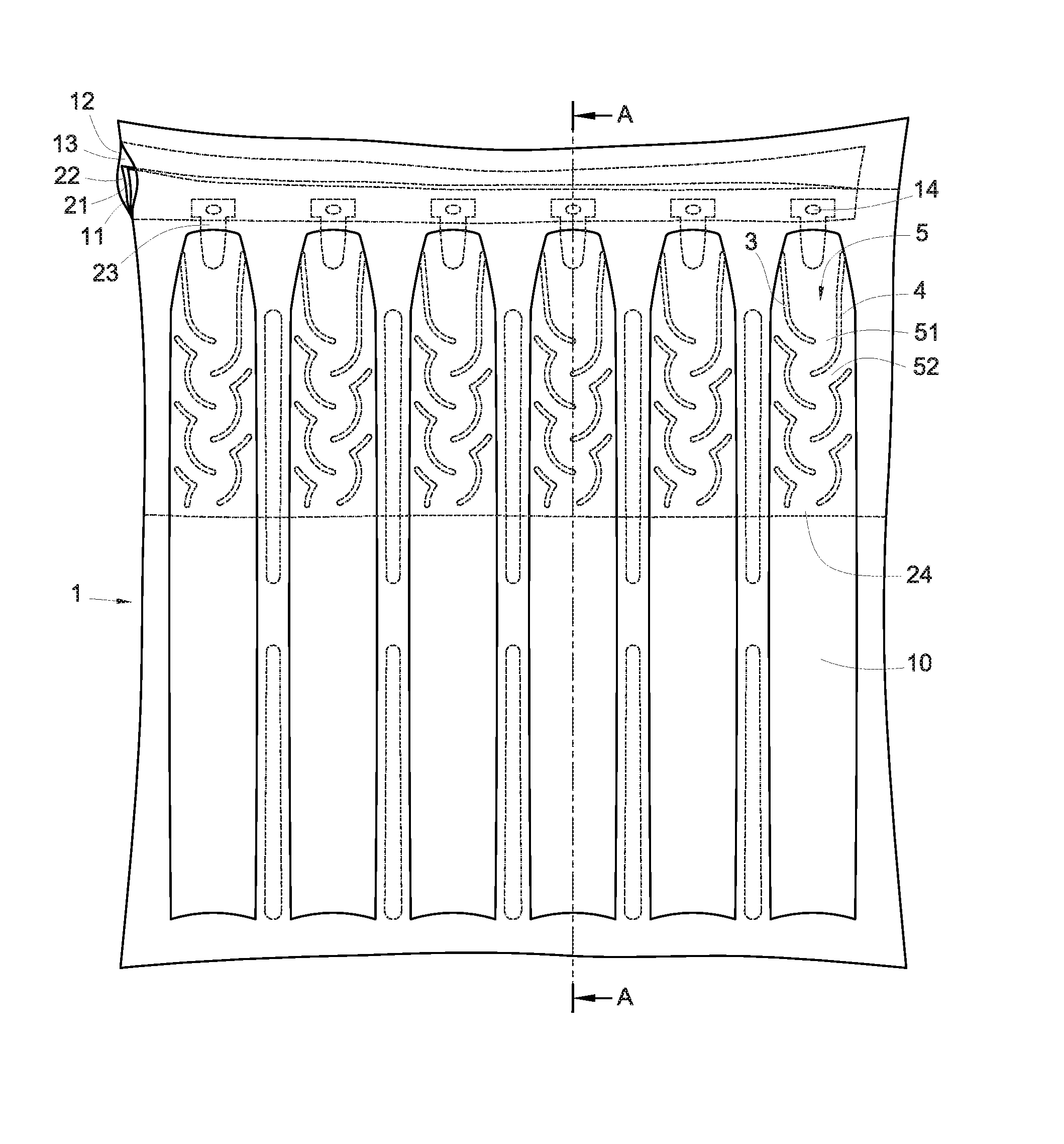
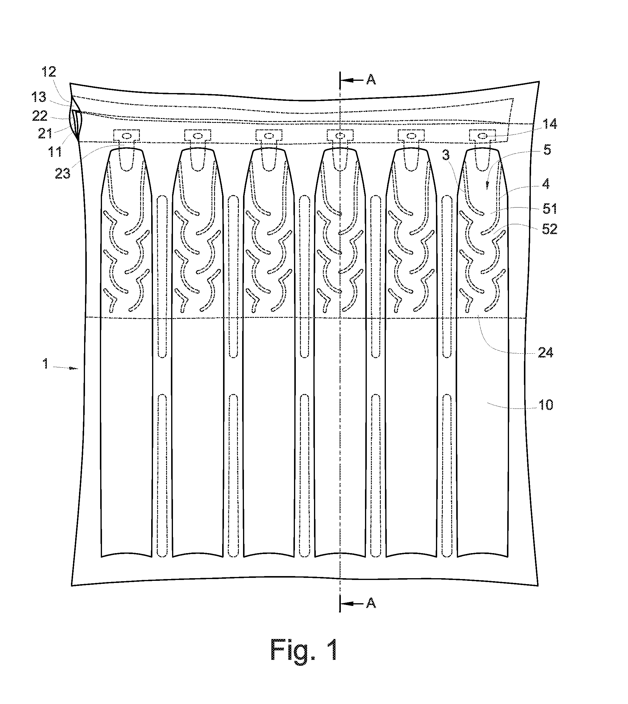
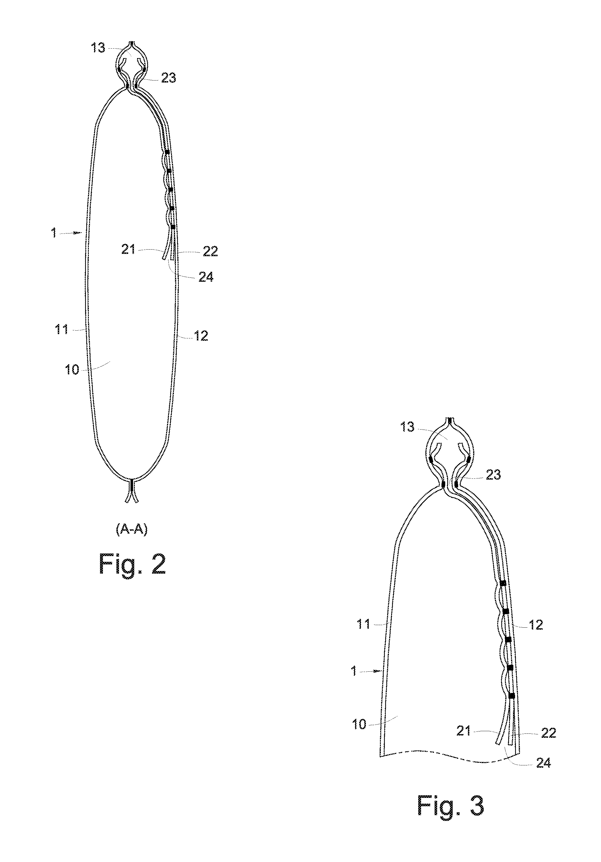
[0035]With reference to FIG. 1 for a front view of a preferred embodiment of the present invention as well as FIGS. 2 to 4, a nonlinear air stop valve structure of the present invention comprises two narrower plastic inner membranes 21, 22 disposed in two wider plastic outer membranes 11, 12, and assembled in an air sealing body 1.

[0036]The inner membranes 21, 22 are hot sealed, such that a plurality of arcs 3, 4 are formed between the inner membranes 21, 22, and disposed on both sides of the inner membranes 21, 22 respectively, wherein the left arcs 3 are disposed on one side of the inner membranes 21, 22, and the right arcs 4 are disposed on the other side of the inner membranes, and both left arcs 3 and right arcs 4 are asymmetrically arranged on left and right sides, and a breach 51 is formed at an end point of the left arc 3 and the right arc 4, and the breach 51 is disposed adjacent to a concave arc surface 33, 43, and plural groups of left and right arcs are arranged on left ...


PUM


Abstract

A nonlinear air stop valve of an air sealing body includes an inner member having left arcs on one side and right arcs on the other side, and both left and right arcs are asymmetrically arranged sideway, and a breach is formed at the bottom of the left and right arcs and on a concave arc surface, and left and right arcs are arranged from top to bottom, such that air entering from an air inlet at the top of the inner membrane flows along an upper arc of the left and right arcs to a lower arc and is blocked by the concave arc surface to flow to the breach and pass through the right arc, breach, left arc and breach in turn from right to left or from left to right into an air outlet at the bottom of the inner membrane and enter into the sealing body.

Description

FIELD OF THE INVENTION[0001]The present invention relates to a nonlinear air stop valve structure, in particular to an air stop valve used in an air sealing body capable of reducing the backflow of air, an inner membrane of the air stop valve, as well as an air inlet, an air outlet, an arc and a breach of the inner membrane.BACKGROUND OF THE INVENTION[0002]In general, an air sealing body includes an airbag for packaging and an airbag for shock absorption, and present existing air sealing bodies usually come with a one-way air stop valve for inflating the air sealing bodies, such that the air sealing body can lock the air automatically after the air sealing body is inflated through the air stop valve.[0003]In addition, the conventional air sealing body is developed into a product with a continuous one-way air stop valve and installed to a continuous air column, such that each independent air column can be fully inflated by a one-time inflation, and after air is passed through the air...

Claims


Application Information

Patent Timeline
Patent Type & Authority Patents(United States)
IPC IPC(8): F16K15/14
CPCB65D81/052Y10T137/7882Y10T137/85938Y10T137/3584
Inventor LIAO, YAW-SHINLIAO, CHIEH-HUA
Owner AIR BAG PACKING
Why Eureka
Try Eureka