Tarp deploying device for rear dump trailer

a technology for deploying devices and dump trailers, which is applied to roofs, load transportation vehicles, vehicle components, etc., can solve the problems of affecting the quality of dump trailers, and affecting the service life of dump trucks

Active Publication Date: 2014-12-16
SIOUX CITY TARP
View PDF4 Cites 10 Cited by
  • Summary
  • Abstract
  • Description
  • Claims
  • Application Information

AI Technical Summary

Benefits of technology

[0008]According to one embodiment the present invention relates to a tarp deploying device that utilizes a double-walled hydraulic hose as a portion of a radial arm to provide flexibility between the radial arm and a tarp roll.
[0009]According to another embodiment, the present invention relates to a tarp deploying apparatus wherein a radial arm is readily detachable from the tarp roll to expose a splined shaft extending from the tarp roll, such that a manual crank can be attached to the splined shaft to permit manual rolling of the tarp.

Problems solved by technology

Therefore, if the trailer bed is not covered as the trailer is pulled over the road, the loose contents may be blown and scattered out of the open top of the trailer bed.
Additionally, the contents of the trailer bed may be compromised by rain, or other contaminants.
Unfortunately these springs can be relatively expensive, are somewhat prone to corrosion, and can be dangerous if not properly covered.
Another disadvantage of existing designs results if the motor or other power source for the tarp roll is not functional.
Under existing designs, there is no satisfactory mechanism for rolling the tarp up.

Method used


Image

  • Tarp deploying device for rear dump trailer
  • Tarp deploying device for rear dump trailer
  • Tarp deploying device for rear dump trailer

Examples


Embodiment Construction

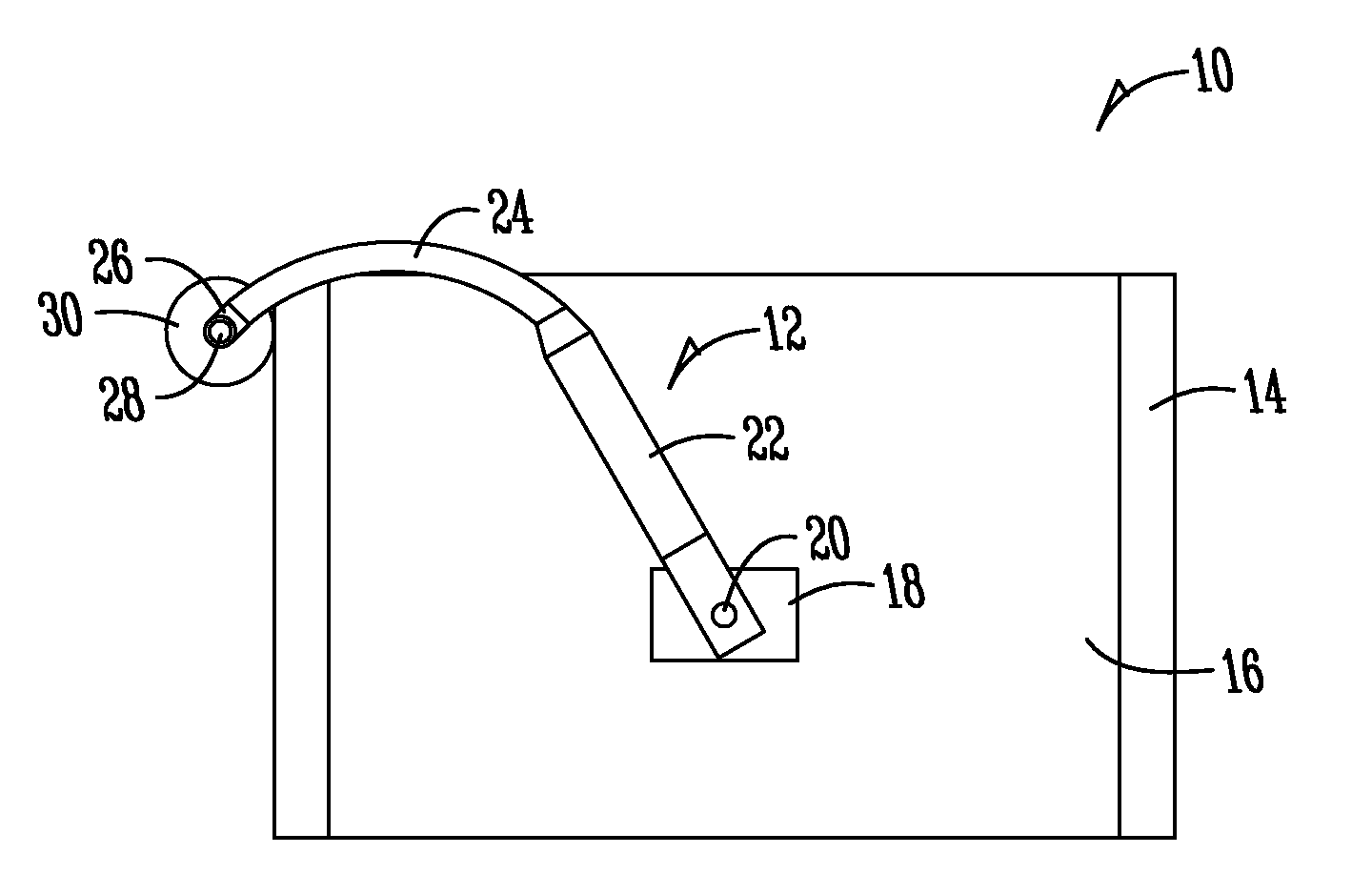
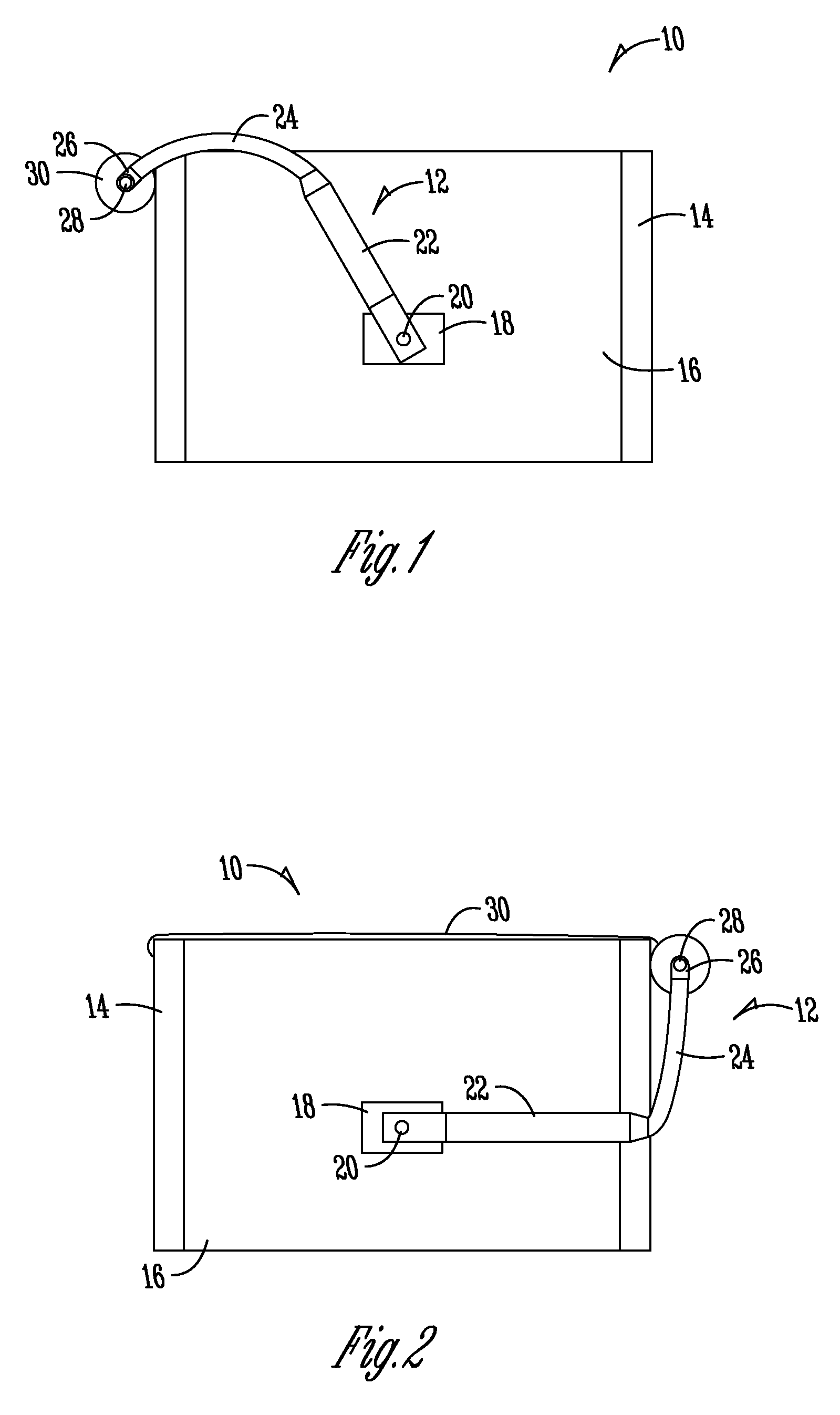
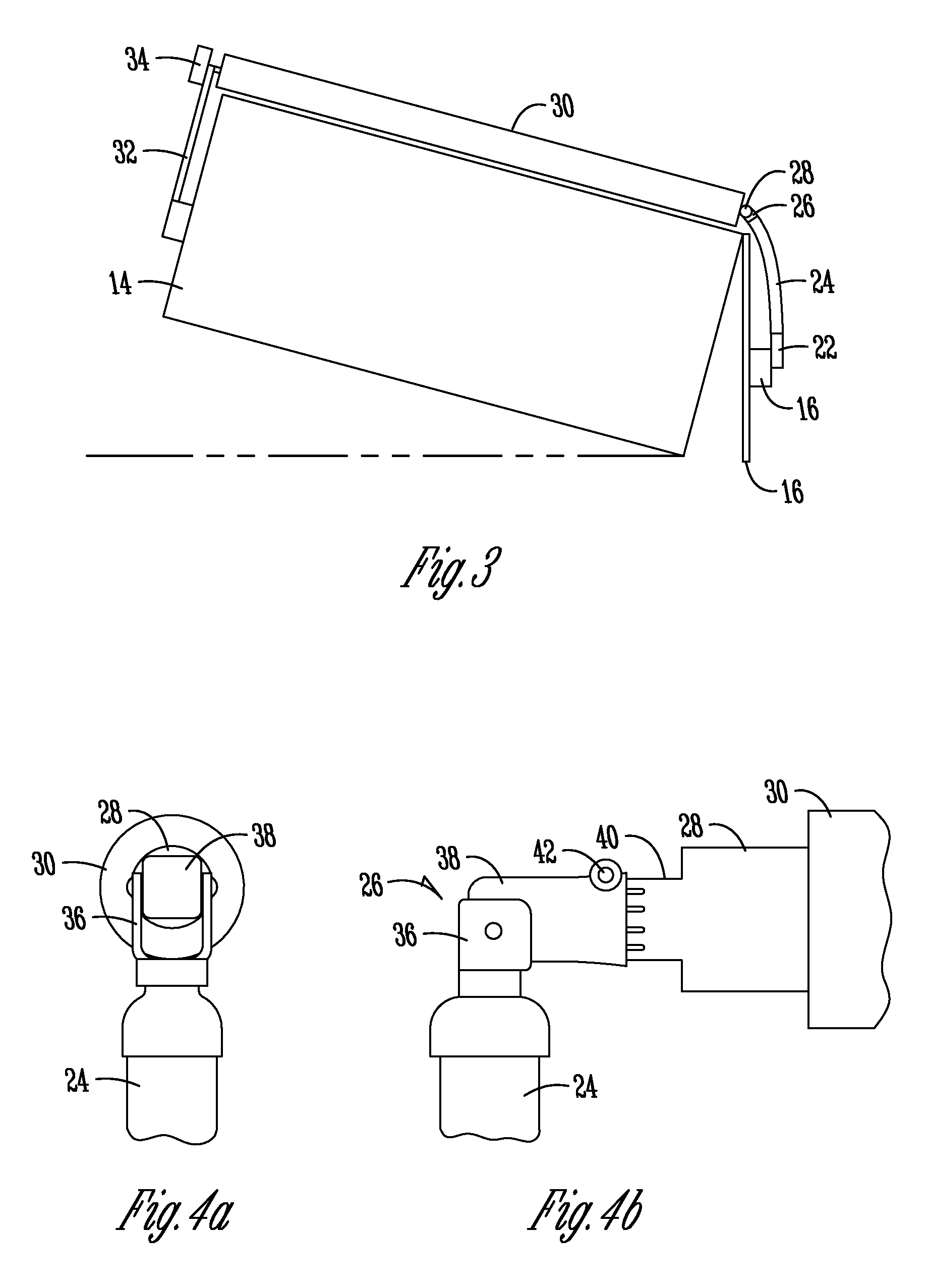
[0024]FIGS. 1 and 2 show a rear dump trailer 10 with a tarp deploying apparatus 12 according to one embodiment of the present invention. The trailer includes a tub 14 with a rear flap or door 16. The flap or door 16 is pivotally mounted near its top to the tub 14 such that it can rotate open when the tub 14 is tilted (see FIG. 3). In FIG. 1 the tarp deploying apparatus 12 is in an open configuration with the top of the tub 14 uncovered. FIG. 2, the tarp deploying apparatus 12 is in a closed or fully deployed configuration, with the tarp 30 covering the tub 14.

[0025]The tarp deploying apparatus 12 includes a mounting bracket 18 fixed to the flap or door 16. The mounting bracket 18 includes a pin 20. A proximal radial arm 22 is pivotally mounted to pin 20. The proximal radial arm 22 should be made of a durable rigid material, such as steel or aluminum. At the free end of the proximal radial arm 22 a flexible distal radial arm 24 is mounted. According to a preferred embodiment, the dis...


PUM


Abstract

A tarp deploying apparatus includes radial arm with a proximal arm and a distal arm. The distal arm is formed from a flexible material such as a double-walled hydraulic hose. The distal arm attaches to a tarp roller having a splined end. The distal arm is selectively removable from the distal arm to permit a hand crank with a female splined socket to be attached to the splined end of the tarp roller to permit hand operation of the tarp deploying system when the electric motor is not functional. A mounting bracket including two feet, a pair of legs and a support span allows easy mounting of the tarp deploying apparatus.

Description

PRIORITY[0001]This application claims priority from U.S. Provisional Application Ser. No. 61 / 756,011, filed Jan. 24, 2013, the entire contents of which are hereby incorporated in their entirety by reference.FIELD OF THE INVENTION[0002]This invention relates generally to the field of tarp deploying devices for use on trailers.BACKGROUND OF THE INVENTION[0003]Trailers used to haul loose materials such as dirt, sand, gravel, or grain commonly have beds or tubs that have an open top with generally vertical front and rear walls and sloping sidewalls for retaining contents within the trailer. Therefore, if the trailer bed is not covered as the trailer is pulled over the road, the loose contents may be blown and scattered out of the open top of the trailer bed. Additionally, the contents of the trailer bed may be compromised by rain, or other contaminants. Accordingly, it is known to deploy tarps across the open top space of the trailer beds to cover the contents of the trailer beds.[0004]...

Claims


Application Information

Patent Timeline
Patent Type & Authority Patents(United States)
IPC IPC(8): B60P7/04B60J11/00
CPCB60P7/04B60J7/085
Inventor BREMER, DONALD, WILLIAM
Owner SIOUX CITY TARP
Why Eureka
Try Eureka