
Quartz showerhead for nanocure UV chamber

a nanocure and shower head technology, applied in the direction of mechanical equipment, coatings, transportation and packaging, etc., can solve the problems of uneven processing, temperature gradient across the substrate, non-uniform gas flow in the uv chamber and process,

Active Publication Date: 2014-12-16
APPLIED MATERIALS INC
View PDF28 Cites 330 Cited by
  • Summary
  • Abstract
  • Description
  • Claims
  • Application Information

AI Technical Summary

Benefits of technology

The patent text describes an apparatus and method for controlling the gas flow profile in a processing chamber. The technical effects of the invention include improved gas flow control for processing materials in the chamber, effective cleaning of the chamber, and reduction of residue buildup on surfaces. The invention involves the use of a transparent showerhead with passages for gas distribution and an upper processing region located between the window and showerhead for injecting gas species, a lower processing region for reacting the gas species with UV light or heat, and a substrate support for positioning the materials during processing. Overall, the invention helps to create a more efficient and effective processing environment.

Problems solved by technology

UV chambers and processes may have non-uniform gas flows through the chamber during the UV curing process to remove porogen.
The non-uniform gas flow may result in uneven heating of the substrate during the curing process, resulting in a temperature gradient across the substrate and uneven processing.
Additionally, the non-uniform build-up of porogen residue on the window may result in unevenly cured film across the substrate.
With time, the porogen residue can reduce the effectiveness of the subsequent UV porogen removal processes by reducing the effective UV intensity available to the substrate and building up at the colder components of the chamber.
Furthermore, the build-up of excessive residues in the chamber can be a source of particulate defects on the substrate which is unsuitable for semiconductor processing.

Method used


Image

  • Quartz showerhead for nanocure UV chamber
  • Quartz showerhead for nanocure UV chamber
  • Quartz showerhead for nanocure UV chamber

Examples


Embodiment Construction

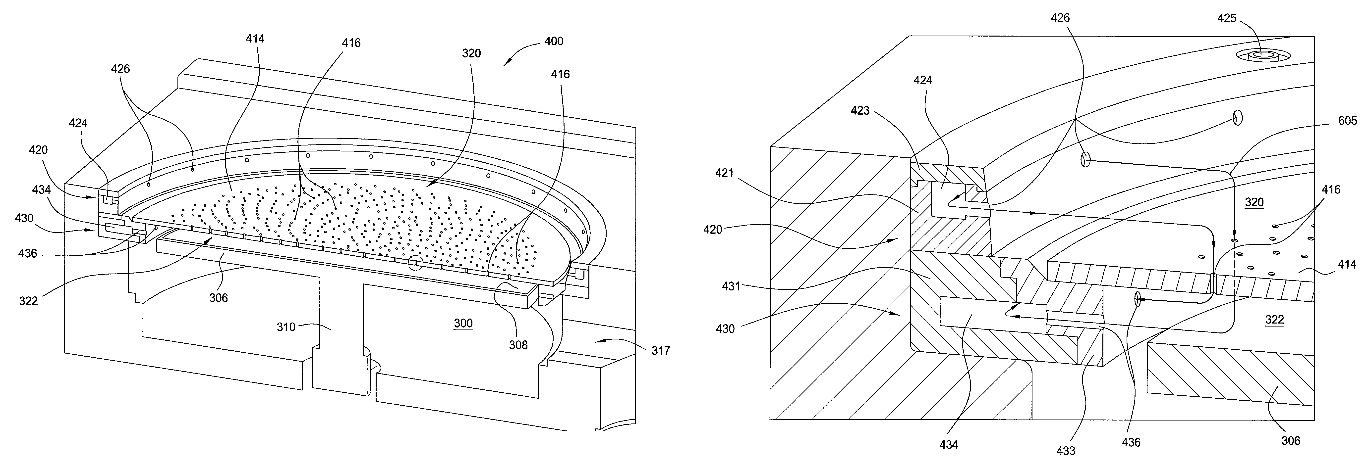
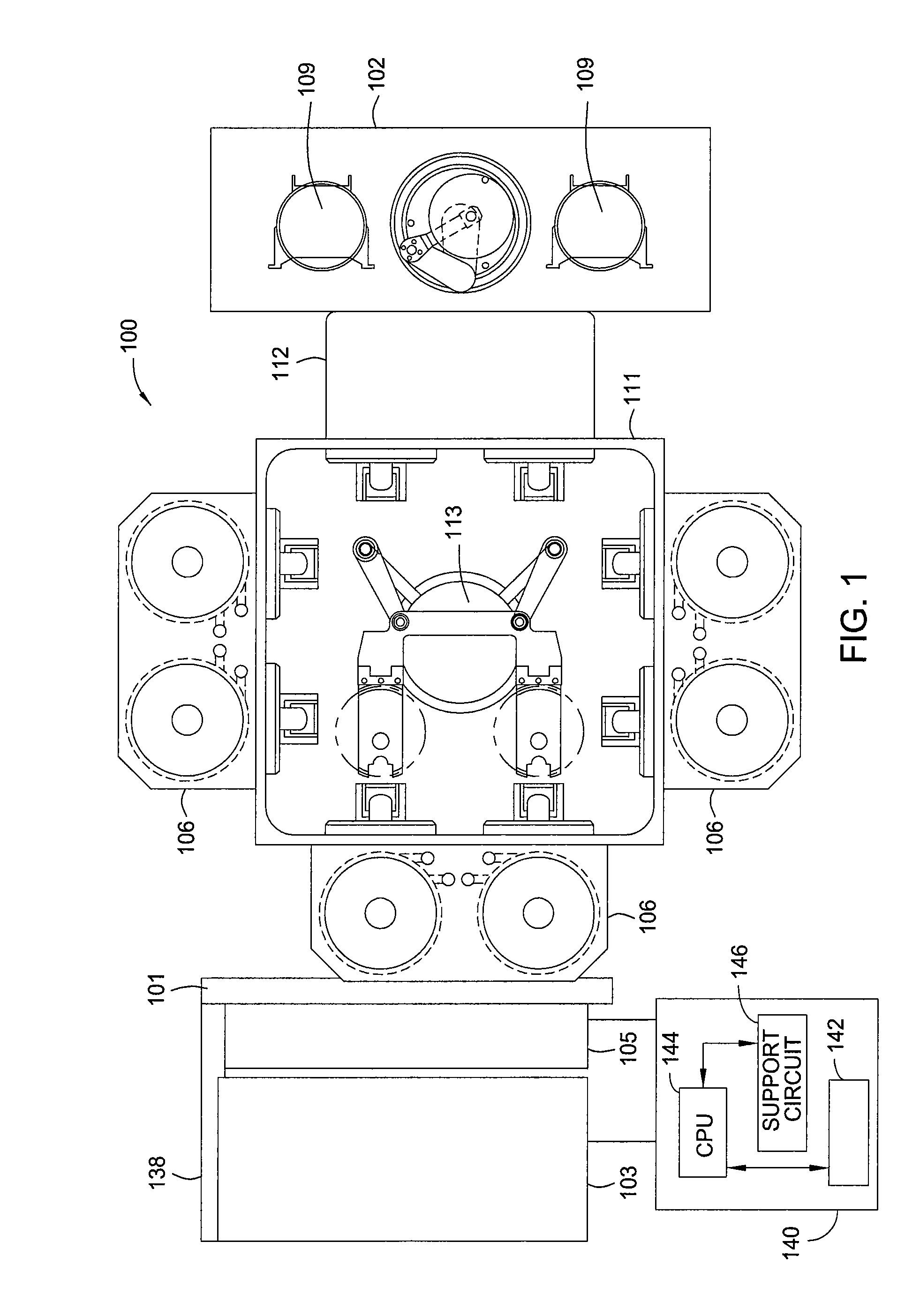
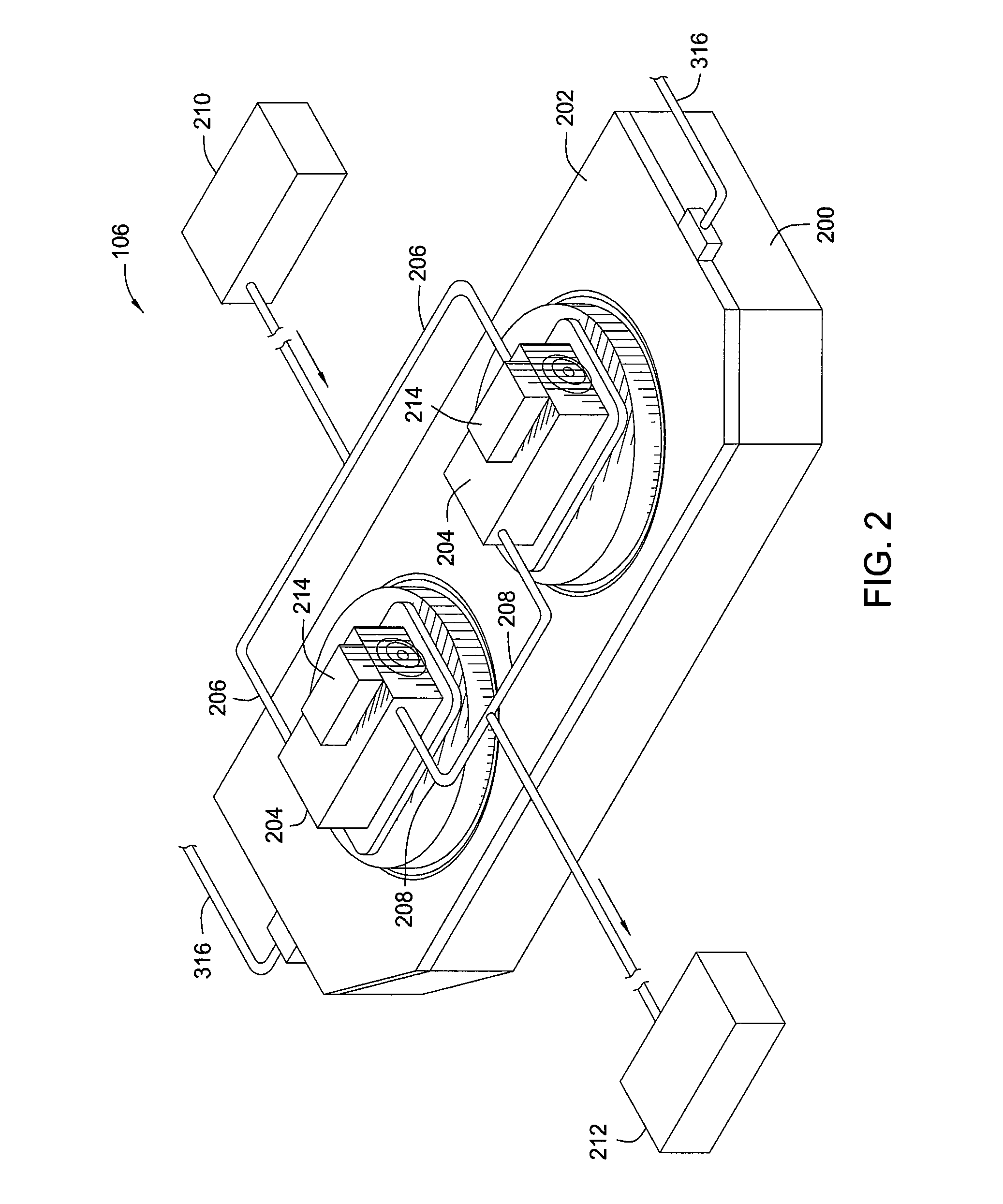
[0026]Embodiments of the invention generally provide a processing tool having an ultraviolet (UV) processing chamber and hardware within the processing chamber for controlling the flow profile within the processing region. Embodiments of the invention enable the processing tool to control the delivery, flow path, distribution, and removal of gases within an ultraviolet processing chamber to better control various processes. Embodiments of the invention also provide methods of controlling the flow profile within a processing tool and a method of cleaning the processing tool.

[0027]The design of the hardware enables a specific flow profile distribution across a substrate being processed within a UV chamber, a lamp heated chamber, or other chambers where energy in the form of light is used to process a film or catalyze a reaction, either directly on or above the substrate. Additionally, the process chamber walls, UV windows, and substrate support may be efficiently cleaned by removing a...


PUM

PropertyMeasurementUnit
dielectric constantaaaaaaaaaa
temperatureaaaaaaaaaa
poweraaaaaaaaaa

Abstract

Embodiments of the invention generally provide apparatuses and methods for controlling the gas flow profile within a processing chamber. In one embodiment, a processing tool includes an ultraviolet processing chamber defining a processing region, a substrate support, a window disposed between a UV radiation source and the substrate support, and a transparent showerhead disposed within the processing region between the window and the substrate support and having one or more transparent showerhead passages between upper and lower processing regions. The processing tool also includes a gas distribution ring having one or more gas distribution ring passages between a gas distribution ring inner channel and the upper processing region and a gas outlet ring positioned below the gas distribution ring, the gas outlet ring having one or more gas outlet passages between a gas outlet ring inner channel within the gas outlet ring and the lower processing region.

Description

CROSS-REFERENCE TO RELATED APPLICATIONS[0001]This application claims benefit of U.S. Provisional Patent Application Ser. No. 61 / 394,711, filed Oct. 19, 2010, which is herein incorporated by reference.BACKGROUND OF THE INVENTION[0002]1. Field of the Invention[0003]Embodiments of the invention relate to processing tools for forming and processing films on substrates, such as with UV light. In particular, embodiments of the invention relate to controlling the gas flow profile within a processing chamber.[0004]2. Description of the Related Art[0005]Materials with low dielectric constants (low-k), such as silicon oxides (SiOx), silicon carbide (SiCx), and carbon doped silicon oxides (SiOCx), find extremely widespread use in the fabrication of semiconductor devices. Using low-k materials as the inter-metal and / or inter-layer dielectric between conductive interconnects reduces the delay in signal propagation due to capacitive effects. The lower the dielectric constant of the dielectric lay...

Claims


Application Information

Patent Timeline
Patent Type & Authority Patents(United States)
IPC IPC(8): C23C16/44C23C16/455C23C16/56H01L21/67H01L21/677C23C16/48
CPCH01L21/67742C23C16/4405H01L21/6719C23C16/482C23C16/45565C23C16/56Y10T137/0391C23C16/45563
Inventor BALUJA, SANJEEVROCHA-ALVAREZ, JUAN CARLOSDEMOS, ALEXANDROS T.NOWAK, THOMASZHOU, JIANHUA
Owner APPLIED MATERIALS INC
Learn More