
Hydrotreating process and controlling a temperature thereof

a technology of hydrotreating process and temperature control, which is applied in the direction of naphtha treatment, treatment with plural parallel refining stages, and treatment with plural parallel stages. it can solve the problems of rapid catalyst deactivation, high and unwanted temperature rise in the reactor bed of the hydrotreating unit, and excessive heat of reaction

Active Publication Date: 2014-12-16
UOP LLC
View PDF21 Cites 6 Cited by
  • Summary
  • Abstract
  • Description
  • Claims
  • Application Information

AI Technical Summary

Benefits of technology

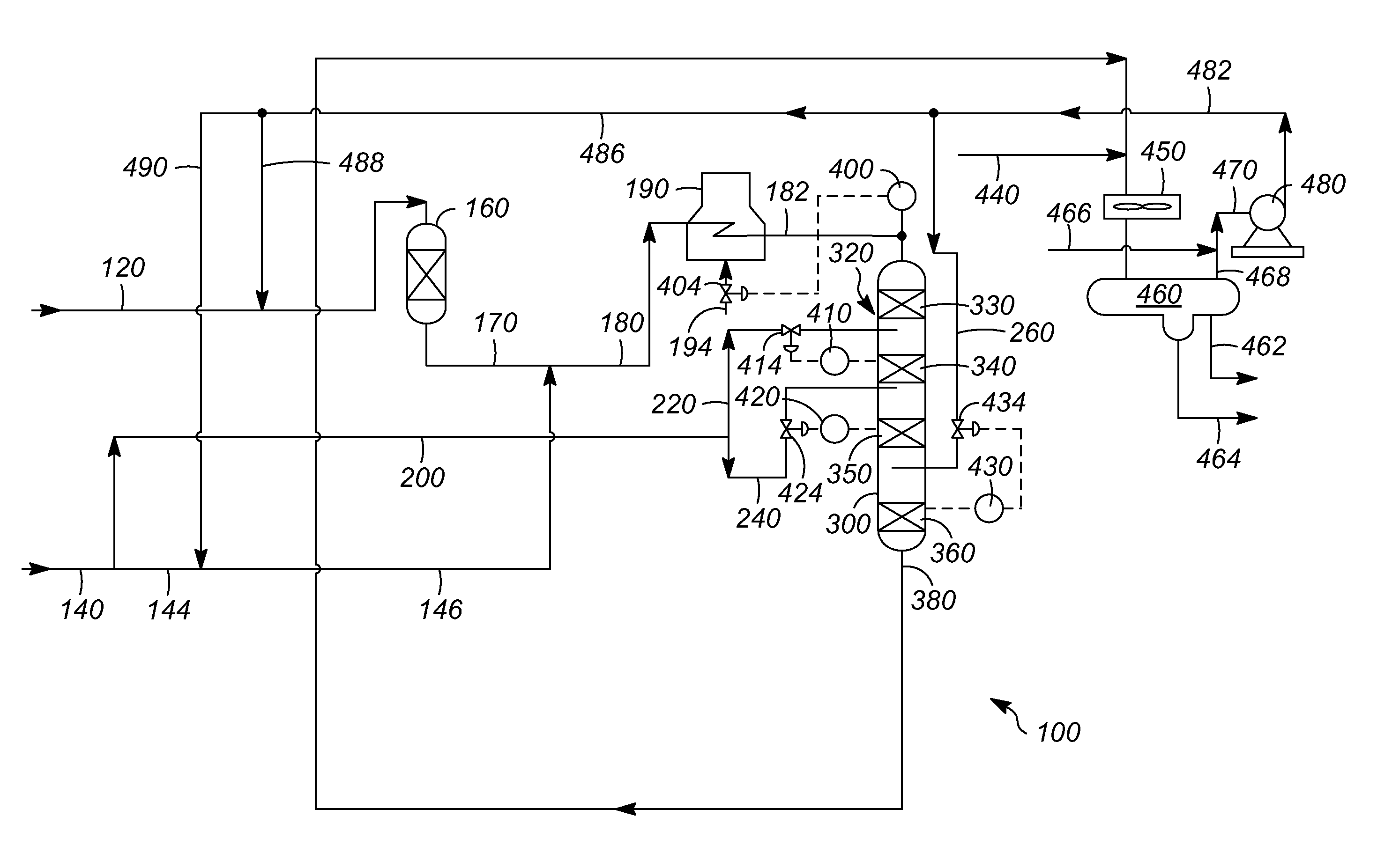
[0008]The embodiments disclosed herein can provide a second naphtha stream in addition to a coker naphtha stream. As a result, the second naphtha stream typically is a straight run naphtha having a diene value of less than about 2 and a bromine number of less than about 10. As a consequence, this stream can have sufficiently low amounts of olefins and diolefins to act as a heat sink in the reactor. Particularly, the second stream can serve as a heat sink by quenching and utilizing sensible as well as latent heat. As a result, the vaporization of the second stream can remove some of the reaction heat without the need of recycling another liquid stream.DEFINITIONS

Problems solved by technology

In hydrotreating coker naphtha, an excessive heat of reaction can be generated.
Additionally, these reactions are often carried out in a vapor phase that can lead to a very high and unwanted temperature rise in the reactor beds of the hydrotreating unit.
The high temperature rise across a bed can cause rapid catalyst deactivation and difficulty in controlling the temperature in subsequent beds.
Moreover, lowering the temperature of the charge furnace outlets might be required to keep the top bed outlet temperature within the design temperature of the reactor, as the temperature rise can be in the range of about 60-about 100° C. However, there is a limit to lowering the furnace outlet temperature due to furnace turn down issues.
As a consequence, this recycling can significantly increase the cost of the unit.

Method used


Image

  • Hydrotreating process and controlling a temperature thereof
  • Hydrotreating process and controlling a temperature thereof

Examples


Embodiment Construction

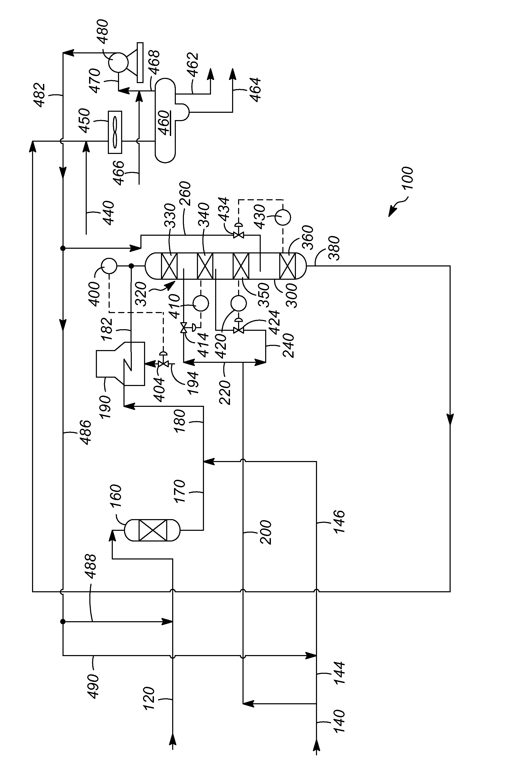
[0023]Referring to the FIGURE, an exemplary hydrotreatment zone 100 can include a diolefin saturation reactor 160, and a hydrotreating reactor 300. The hydrotreatment zone 100 can receive a first feed stream 120 and a second or another feed stream 140. The first feed stream 120 can include a naphtha with a diene value of greater than about 2 and a bromine number of about 10-about 120, and is usually a coker naphtha. The olefins in the first feed stream 120 can range anywhere from about 15-about 55%, by volume, and hence a reactor bed temperature rise can be high due to the heat of reaction associated with olefin saturation. The second feed stream 140 can include an effective amount of olefins and diolefins, typically with a diene value of less than about 2 and a bromine number of less than about 10. Typically, the second feed stream 140 can be a straight run naphtha and has sufficiently low amounts of olefins and diolefins to act as a quench in the hydrotreating reactor 300. General...


PUM

PropertyMeasurementUnit
bromine numberaaaaaaaaaa
temperatureaaaaaaaaaa
bromine numberaaaaaaaaaa

Abstract

One exemplary embodiment can be a hydrotreating process. The hydrotreating process can include providing a first feed stream having a coker naphtha with a bromine number of about 10-about 120, combining the first feed stream with a second feed stream having a straight run naphtha with a bromine number of less than about 10 to create a combined feed, providing the combined feed to a hydrotreating reactor having at least one catalyst bed, and separating a quench stream from the second feed stream and providing the quench stream after the at least one catalyst bed.

Description

FIELD OF THE INVENTION[0001]This invention generally relates to a hydrotreating process and controlling a temperature thereof.DESCRIPTION OF THE RELATED ART[0002]In hydrotreating coker naphtha, an excessive heat of reaction can be generated. Additionally, these reactions are often carried out in a vapor phase that can lead to a very high and unwanted temperature rise in the reactor beds of the hydrotreating unit. The high temperature rise across a bed can cause rapid catalyst deactivation and difficulty in controlling the temperature in subsequent beds. Moreover, lowering the temperature of the charge furnace outlets might be required to keep the top bed outlet temperature within the design temperature of the reactor, as the temperature rise can be in the range of about 60-about 100° C. However, there is a limit to lowering the furnace outlet temperature due to furnace turn down issues. As a consequence, various techniques may be employed to mitigate the temperature rise.[0003]One t...

Claims


Application Information

Patent Timeline
Patent Type & Authority Patents(United States)
IPC IPC(8): C10G45/38
CPCC10G45/38C10G2300/1044C10G2300/4006C10G65/06C10G49/04C10G65/04C10G45/32C10G45/08
Inventor BANERJEE, SOUMENDRAHOEHN, RICHARDVARADARAJAN, SRINIVASA GOPALAN
Owner UOP LLC
Learn More