Brake lining for railroad car

a technology for railroad cars and brakes, which is applied in the direction of friction linings, mechanical devices, transportation and packaging, etc., can solve the problems of increasing the temperature of the contact surface, local rise in temperature, and the inability of the elastic member to effectively achieve the inherent uniform surface pressure function, so as to prevent deformation and deterioration of the elastic member, uniform surface pressure, and uniform surface pressure

Inactive Publication Date: 2014-12-30
NIPPON STEEL CORP
View PDF12 Cites 12 Cited by
  • Summary
  • Abstract
  • Description
  • Claims
  • Application Information

AI Technical Summary

Benefits of technology

[0021]According to the present invention, the surfaces of the friction members are formed in a convex curved shape which faces the back plate so that when heavy pressing force is applied, the convex curved shape portions make contact with the back plate, and the pressing force is directly transmitted to the friction members, thereby making it possible to prevent deformation and deterioration of the elastic members which are disposed between the friction members and the back plate, and to achieve a uniform surface pressure.
[0022]It is possible to maintain the uniform surface pressure as much as possible, with the load being widely distributed by the convex curved shape portions, even when heavy pressing force is applied, because the friction members are formed in a convex curved shape which faces the back plate, with their outer peripheral surfaces disposed away from the elastic members.

Problems solved by technology

When it works, the temperature of a contact surface of the brake lining and the brake disc rises due to a frictional heat, and with an increasing speed of the vehicle, the temperature of the contact surface rises due to an increased brake load.
As a consequence, the contact surface pressure between the brake lining and brake disc increases directly beneath the location where the pressing force operates, producing a local rise in temperature.
However, the technology disclosed in Patent Reference 1 interposes an elastic member when attaching a the friction member to the back plate, so that when a pressing force operates, the friction member increases in temperature, and the elastic member yields, subsequently making it impossible for the elastic member to effectively achieve its inherent uniform surface pressure function.
However, in the technologies disclosed in Patent References 2 and 3, the uniform surface pressure function is lost if the components of the spherical-seated structure undergo plastic deformation due to the pressing force.

Method used


Image

  • Brake lining for railroad car
  • Brake lining for railroad car
  • Brake lining for railroad car

Examples


examples

[0031]The preferred embodiment of the present invention is described below, along with the process from conceptualizing the present invention to solving the problem of the prior art.

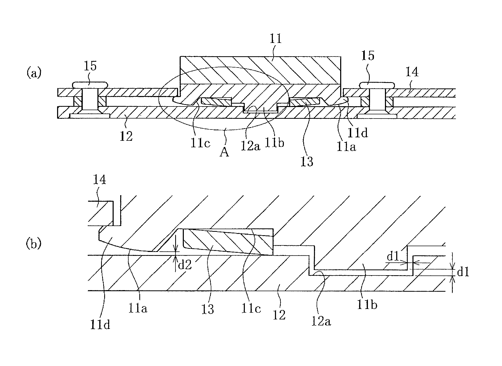
[0032]The present inventors considered the fact that when a heavy pressing force is applied, the temperature of a friction member rises, causing a yield of the elastic member disposed between the friction member and the back plate, and the present inventors realized that it would be effective to limit the use of the elastic member when a heavy pressing force is applied, in order to maintain the uniform surface pressure function of the elastic member over a long period of time.

[0033]The present inventors also determined that when a heavy pressing force is applied, a sufficient uniform surface pressure can be achieved by means of an elasticity of the friction member itself and by means of an elasticity of the lining device as a whole, even if the function of the elastic member is not employed.

[0034]The bra...


PUM


Abstract

A brake lining for a railroad car brake includes friction members which are pressed onto the sliding surface of a brake disc, and a back plate which is attached to a brake caliper in order to support the friction members. The friction members are dividedly arranged in a radial direction and in a circumferential direction of the brake disc. A disc spring is disposed between each respective friction member and the back plate. An outer peripheral surface of the friction members facing the back plate is formed in a convex curved shape in an area outside the elastic member. When a light pressing force is applied, a pressing force is transmitted from the back plate to the friction members via the disc springs. When a heavy pressing force is applied, the back plate and a rounded surface portion make contact, thereby directly transmitting a pressing force to the friction members.

Description

TECHNICAL FIELD[0001]The present invention relates to a brake lining for a railroad car which effectively distributes thermal energy generated by friction against a brake disc, thereby making it possible to increase the durability of both the brake lining and the brake disc.BACKGROUND ART[0002]With the increased speed and greater size of land transportation machinery such as railroad cars and automobiles, as well as motor bicycles and the like, disc brakes have come to be widely used as braking devices for such vehicles.[0003]Following is a description of an example of a disc brake used for a railroad car.[0004]A disc braking system operates a brake caliper which presses a brake lining on a sliding surface of a brake disc mounted onto an axle or a wheel so as to produce a braking force and thereby control the speed of a vehicle by damping the rotation of the axle or the wheel.[0005]When it works, the temperature of a contact surface of the brake lining and the brake disc rises due t...

Claims


Application Information

Patent Timeline
Patent Type & Authority Patents(United States)
IPC IPC(8): B61H5/00F16D55/00F16D65/092
CPCB61H5/00F16D65/092F16D69/0408F16D2069/0433
Inventor HIRAMATSU, SHINICHIROKATO, TAKANORI
Owner NIPPON STEEL CORP
Why Eureka
Try Eureka