Wireless spout and system for dispensing

a technology of wireless spouts and wire spouts, which is applied in the field of wireless spouts and systems for dispensing, can solve the problems of high power consumption, unfavorable precise control of liquid pouring, and inability to use pouring stoppers for hand pouring

Active Publication Date: 2015-01-06
L2F INC
View PDF55 Cites 9 Cited by
  • Summary
  • Abstract
  • Description
  • Claims
  • Application Information

AI Technical Summary

Benefits of technology

[0014]One of the benefits provided by embodiments of the invention described herein is that a silicone tube inside the spout is a path for the liquid to pass through from the bottle without any restrictions. Meanwhile, the rest of the components are protected or isolated from liquid and are thus per se not necessary to be liquid-resistant or liquid-proof. This also guarantees a quick and controlled flow of the liquid and avoids any air bubbles to influence the pour precision.
[0015]The silicone tube can be easily squeezed to stop the liquid flow. This can be done by a stepping motor, a motor with gearbox, or any other motor or appropriate mechanism.
[0016]To ensure that the dosing of liquid from the pour spout is uniform and accurate, it is advantageous that a liquid indicator is sealed into the silicone tube. This makes it possible to register liquid flowing out of the pourer during the entire period of time, whether pre- or not pre-determined.

Problems solved by technology

Even with this additional control unit outside, due to a control time lapse and difference in position between detection and control, it is unlikely to have precise control in pouring of liquid.
The coil itself is seated externally on a bottle holder, which means that the pouring stopper cannot be used for hand pouring.
However, the magnetizable rod and coil use power the entire time that the spout is open, which requires high power consumption.
Additionally, the electronic parts are not liquid proof, risking the chance that the liquid may wet or dampen them.

Method used


Image

  • Wireless spout and system for dispensing
  • Wireless spout and system for dispensing
  • Wireless spout and system for dispensing

Examples


Embodiment Construction

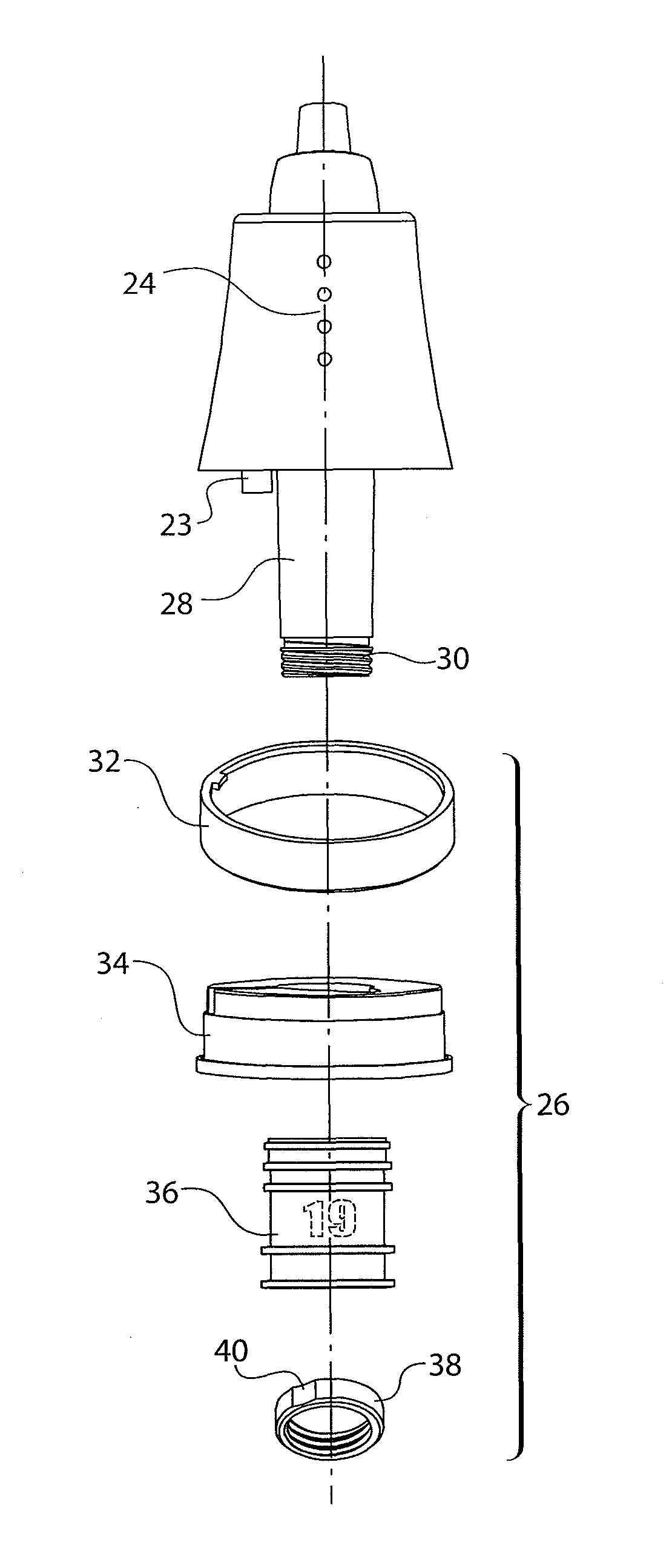
[0036]The indicator system with different visual indicia configured to indicate a selected pour size and the attachment system comprising a removable and replaceable cork and nut are described below in detail.

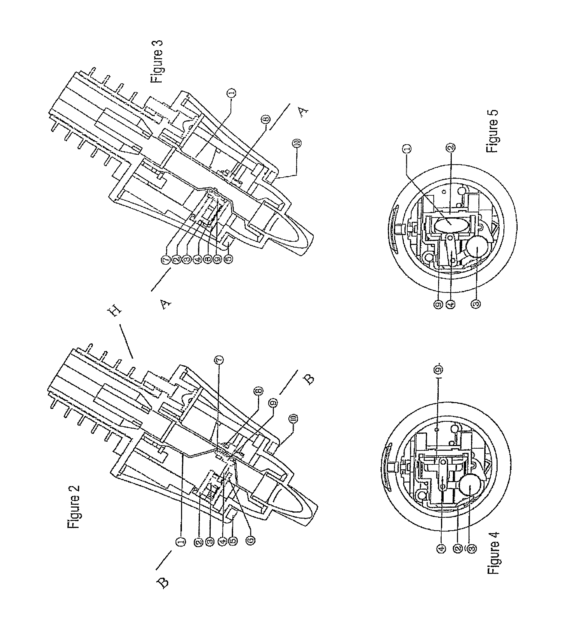
[0037]FIGS. 2-5 show a pouring device mounted onto a container (not shown) for dosing of a liquid. The pouring device has a compact housing H configured to seal an opening of the container. A passage (which is at least one portion being in the form of a flexible silicone tube 1 is provided within the housing H for liquid to pass through. An opening / closing mechanism disposed within the compact housing opens or closes the passage in order to dose a predetermined or registerable amount of liquid. In order to close the passage, the silicone tube 1 is squeezed / pressed by the opening / closing mechanism to block the passage. The passage / silicone tube is preferably normally closed as shown in FIG. 2 (but it might be normally open in some cases), and the dosing of liquid is activated by...


PUM

PropertyMeasurementUnit
angleaaaaaaaaaa
sizesaaaaaaaaaa
sizeaaaaaaaaaa

Abstract

Embodiments of the present invention provide a pouring device for a container for the dosing of liquid. The pouring device has various features intended to ease use, including an improved removal and attachment system and a system to identify and visually illustrate selected pour sizes. In a specific embodiment, the pouring device has a colored light or LED indicator system that allows the user to quickly and easily confirm the selected pour size. Embodiments may also include one or more features that ease attachment and removal of the pouring device to a liquid container, such as a replaceable cork system.

Description

CROSS-REFERENCES TO RELATED APPLICATIONS[0001]This application is a continuation-in-part of U.S. application Ser. No. 12 / 117,230, filed May 8, 2008 titled “Wireless Spout System for Free- and Pre-Measured Dispensing,” the entire contents of which are hereby incorporated by reference.FIELD OF THE INVENTION[0002]Embodiments of the present invention relate generally to systems for monitoring the amount of liquid poured from liquid containers. Further embodiments relate to systems designed to ease positioning and removal of monitoring systems on liquid containers. Even further embodiments relate to improved systems for indicating selected pour sizes.BACKGROUND OF THE INVENTION[0003]The amount of liquid dispensed from liquid containers needs to be monitored for many endeavors today. For instance, the management of establishments has long found it necessary to carefully monitor the relationship between liquor dispensed and receipts by controlling the quantity of liquor dispensed from a sp...

Claims


Application Information

Patent Timeline
Patent Type & Authority Patents(United States)
IPC IPC(8): B67D3/00B67D1/00B65D25/48B67D3/04G01F13/00G01F15/075
CPCB67D3/0006B65D25/48B67D3/0003B67D3/0041B67D3/041G01F13/006G01F15/075Y10T29/49826
Inventor ZAPP, ACHIM PHILIPPMARTINDALE, RICHARD A.
Owner L2F INC
Why Eureka
Try Eureka