Multicomponent foil-type container

a multi-component, foil-type technology, applied in the direction of pliable tubular containers, packaging goods types, transportation and packaging, etc., can solve the problems of large mixing volume, high squeezing resistance, and inability to modify without additional means, etc., to achieve convenient opening, simple deflection elements, and efficient mixing

Inactive Publication Date: 2011-05-03
SULZER MIXPAC AG
View PDF27 Cites 14 Cited by
  • Summary
  • Abstract
  • Description
  • Claims
  • Application Information

AI Technical Summary

Benefits of technology

[0005]For the multicomponent foil type container according to the invention, significantly more complex deflection elements and mixing structures can be realized by the separate mixing element, whereby particularly efficient mixing is allowed. The seal of the chambers of the multicomponent foil type container can be opened easily by the elongated end of the mixing element facing the chambers and the one or more opening pins arranged on this mixing element for opening the one or more seals. In comparison with conventional multicomponent containers of this type, the components need not be pre-mixed by squeezing them back and forth several times in order to achieve good mixing. The separate mixing element allows a particularly effective construction and arrangement of the deflection element, whereby the mixing volume is also reduced. The short flow paths in the mixer and the compact mixer structure allow easy squeezing of the components. The handling of the multicomponent foil type container is extremely simple and requires no complicated preparations. The container merely must be pressed together in the area of the two chambers by hand, whereby the two components are forced through the mixing element and mixed there without a great expenditure of force. Due to the separate mixing element, the multicomponent foil type container can also be adapted relatively easily to different requirements and components. According to the type and properties of the components, a suitable mixer can also be selected without large production-specific changes either during production or also just before use.
[0006]In a particularly advantageous construction, the chambers are constructed in two half-shells, which are produced from a flexible but nevertheless dimensionally stable material. The two half-shells can be filled easily and then assembled together. The dimensionally stable material can prevent the chambers from bulging out during the pressing process, so that the entire applied pressure is available for pressing the components out of the chambers into the discharge duct.
[0007]For a simple construction in terms of production, the discharge duct is formed by two groove-shaped indentations in the two half-shells. The chambers for storing the components, however, can also be arranged in a separate storage part and the discharge duct can be arranged in a discharge tube that can be attached to the storage part. In this way, discharge tubes with different mixing elements can be provided for different components.
[0008]The seal for preventing mixing of the components before use can be formed by one or more separating films arranged between the two chambers. The seal, however, can also be formed by separating crosspieces or separating walls between the chambers and the discharge duct.

Problems solved by technology

Due to the deflection elements formed on the container films, however, the possible constructions of the mixing structures are limited, so that a relatively large mixing volume is required for achieving effective mixing.
In addition, due to the limited embodiments of such a mixer, very long flow paths are required for the components to be mixed, in order to achieve adequate mixing, which results in high squeezing resistance.
In addition, the deflection elements are tailored to certain components and fields of use and cannot be modified without additional means.

Method used


Image

  • Multicomponent foil-type container
  • Multicomponent foil-type container
  • Multicomponent foil-type container

Examples


third embodiment

[0057]The third embodiment shown in FIGS. 5 and 6 differs from the previously mentioned constructions essentially in that the groove-shaped indentations 7 and 7′ have inclined parts 15 and 15′, respectively, elongated on the chamber-side end and arranged next to an area 16 and 16′ of the chambers 5 and 5′, respectively, elongated towards the front. As follows from FIG. 6, the inclined part 15 of the indentation 7 and the chamber 5 are arranged one next to the other with its elongated area 16 so that the inclined parts 15 and 15′ of one hall-shell each overlap the elongated areas 16 and 16′ of the other half-shell when the identical half-shells 1 and 2 are placed one on top of the other. Opening pins 17 and 17′, which can be pressed from the outside, which project inwards, and which can be made to pierce through the separating film or films 12 arranged between the half-shells 1 and 2 by hand without damaging the outer skin of the container, are arranged on the two inclined parts 15 a...

fourth embodiment

[0058]In the fourth embodiment shown in FIGS. 7 and 8, a separate discharge tube 18 with the discharge duct 6 arranged therein is provided. The discharge tube 18 can be set on a separate storage part 19 of the multicomponent foil type container at this point. The storage part 19 is here composed of two identical half-shells 1 and 2, in which the chambers 5 and 5′ formed by bulges are located. The two chambers 5 and 5′ are also here filled with different components. The seal is realized here by a separating film 12 arranged between the half-shells 1 and 2 and by a front separating wall 21 of the half-shells 1 and 2. The chambers 5 and 5′ are separated from the discharge duct 6 of the discharge tube 18 before use by the front separating walls 21 of the two half-shells 1 and 2. The discharge tube 18 can be connected to the storage part 19 sealed from the outside by means of a sleeve-shaped attachment part 20. To connect the chambers 5 and 5′ to the discharge duct 6, the separating wall...

fifth embodiment

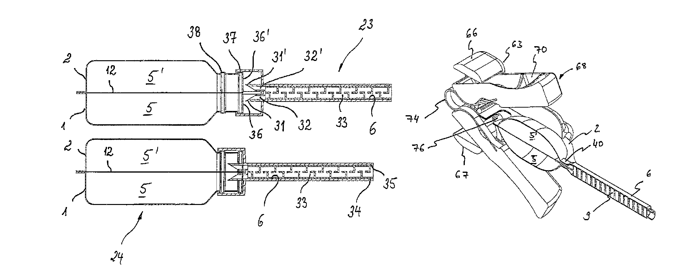
[0059]In the fifth embodiment shown in FIGS. 9 and 10, a discharge tube 23 is attached to a storage part 24 displaceable in the longitudinal direction. The storage part 24 is composed, in turn, from two identical half-shells 1 and 2, in which the chambers 5 and 5′ formed from indentations are constructed. Here, the two chambers 5 and 5′ are also separated from each other by a separating film or films 12 arranged between the half-shells 1 and 2. Within the half-shells 1 and 2 there are separating walls 25 and 25′, which prevent the discharge of the components into the discharge duct 6 before use. The discharge tube 23 is constructed for this configuration such that the mixing element 9 can be inserted from the discharge opening into the discharge duct 6.

[0060]As shown in FIG. 10, the discharge tube 23 is attached by means of a hollow cylindrical attachment piece 26 onto a throat 27 of the storage pan 24 with a round cross section displaceable in the longitudinal direction. The axial ...


PUM


Abstract

The invention relates to a multicomponent foil-type container comprising a first chamber (5) for accommodating a first component, at least one second chamber (5′) for accommodating a second component, a discharge duct (6) that can be connected to said chambers (5, 5′), deflection elements (11) for mixing the components within the discharge duct (6), and a seal (12; 12′; 21; 25, 25′; 36, 36′) which prevents the components from being mixed before being used and can be opened for discharging the components. The deflection elements (11) of the inventive multicomponent foil-type container are disposed on a separate mixing element (9) that is located in the discharge duct (6) such that the multicomponent foil-type container is easy to produce while allowing different components to be mixed in a particularly effectively manner. The invention further relates to a device for squeezing a multicomponent foil-type container in a particularly effective fashion. The disclosed squeezing device is provided with a holding element (61; 77) for accommodating a multicomponent foil-type container. At least one leg (68, 69; 88) that can be moved towards the chambers (5, 5′) of the multicomponent foil-type container in order to squeeze the multicomponent foil-type container is hingedly connected to the end of the holding element (61; 77) which faces the rear end of an inserted multicomponent foil-type container, resulting in the components being effectively mixed.

Description

FIELD OF THE INVENTION[0001]The invention relates to a multicomponent foil type container. The invention further relates to a container arrangement with several such multicomponent foil type containers and also to a squeezing device for a multicomponent foil type container.BACKGROUND OF THE INVENTION[0002]A multicomponent foil type container of this class is known from U.S. Pat. No. 4,952,068. There the multicomponent foil type container is formed by two relatively thin and flexible plastic films, which border a first and a second chamber for accommodating the two different components of a two-component adhesive. Both chambers have outlet openings in a mixing area, wherein the components are held back in an unmixed state by separating films in the chambers before use. For squeezing out the components, the container is pressed together in the area of the chambers, so that the separating films break open and the two components are led into the mixing area. Deflection elements, by mean...

Claims


Application Information

Patent Timeline
Patent Type & Authority Patents(United States)
IPC IPC(8): B01F15/02B01F5/06B65D25/08
CPCB01F5/064B01F15/0205B01F15/0226B65D35/28B65D81/3261B65D81/3283B65D51/222B65D2251/0093B65D2251/0025B01F25/432B01F35/713B01F35/7164
Inventor HEUSSER, ROLFGASSER, MARKUSSTAUB, ANDREAS
Owner SULZER MIXPAC AG
Why Eureka
Try Eureka