Wayside measurement of railcar wheel to rail geometry

a technology of geometry and railcar, applied in distance measurement, instruments, transportation and packaging, etc., can solve the problems of increasing wear, wheel flange impacting the rail, rapid component wear, etc., to reduce labor-intensive alignment and calibration procedures, reduce the effect of dust/snow wake, and eliminate errors

Active Publication Date: 2015-01-06
INT ELECTRONICS MACHINES
View PDF36 Cites 39 Cited by
  • Summary
  • Abstract
  • Description
  • Claims
  • Application Information

AI Technical Summary

Benefits of technology

[0011]An embodiment can acquire all data required to make a measurement simultaneously (as opposed to over a period of time) to eliminate errors associated with wheelset transverse and / or angular motion that may occur when measurements are made over a more extended period of time.
[0012]An embodiment can provide, within the acquired data, a reference to the rail tangent line, reducing the need for labor intensive alignment and calibration procedures at installation and periodically during operation.
[0013]An embodiment can acquire sufficient data points over an extended portion of a wheel so as to be insensitive to isolated surface anomalies that may be present on the wheel due to normal use.
[0014]An embodiment can mitigate the effects of the wake of dust / snow that may result from a train passing at high speed.
[0015]An embodiment can prevent accidental injury to the eyes of railway maintenance personnel or other persons that may be in the path of the operating invention by utilizing laser power levels classified as eye safe under all conditions.

Problems solved by technology

Minimum wear on components and maximum ride comfort occurs when the wheelsets are centered on the rail with axes of rotation perpendicular to the rail centerline; any deviation from this alignment and orientation introduces vibration and results in increased wear.
Finally, hunting is a term describing periodic transverse motion of the railcar on the track that may, in severe cases cause resonant oscillation, which results in the wheel flanges impacting the rail.
This condition can result in rapid component wear and serious ride comfort issues.
Serious truck geometry errors can even result in derailment, especially when operating at high speed and when cornering, causing considerable damage and potential loss of life.
Such a system, however, requires expensive and time consuming changes to the track infrastructure.
If the instrumented rail sections are changed out, the system functionality will be lost.
Unfortunately, this approach is only robust for new, good-condition wheels.
However, as the wheel wears, the rim face becomes more and more narrow, resulting in two separated measurement regions which become smaller as the wheel continues to wear.
As the corners of the rim face may be contaminated with debris, dirt, snow, ice, or the like, inconsistent measurements may result, especially in the case of the more worn wheels for which the measurements have less redundancy to allow for the elimination of outliers.
Another significant limitation of this approach derives from the fact that the measured points are in a time-sequence along a moving object.
As there are modes of movement of the wheels in which the alignment of the wheel will vary throughout a complete revolution, this method of measurement may be confused or at least rendered less accurate through variations in the wheel orientation over time.
In particular, proximity sensors are known to have response variations to all of these conditions, and any variation in response can result in an incorrect measurement of the target parameters.

Method used


Image

  • Wayside measurement of railcar wheel to rail geometry
  • Wayside measurement of railcar wheel to rail geometry
  • Wayside measurement of railcar wheel to rail geometry

Examples


Embodiment Construction

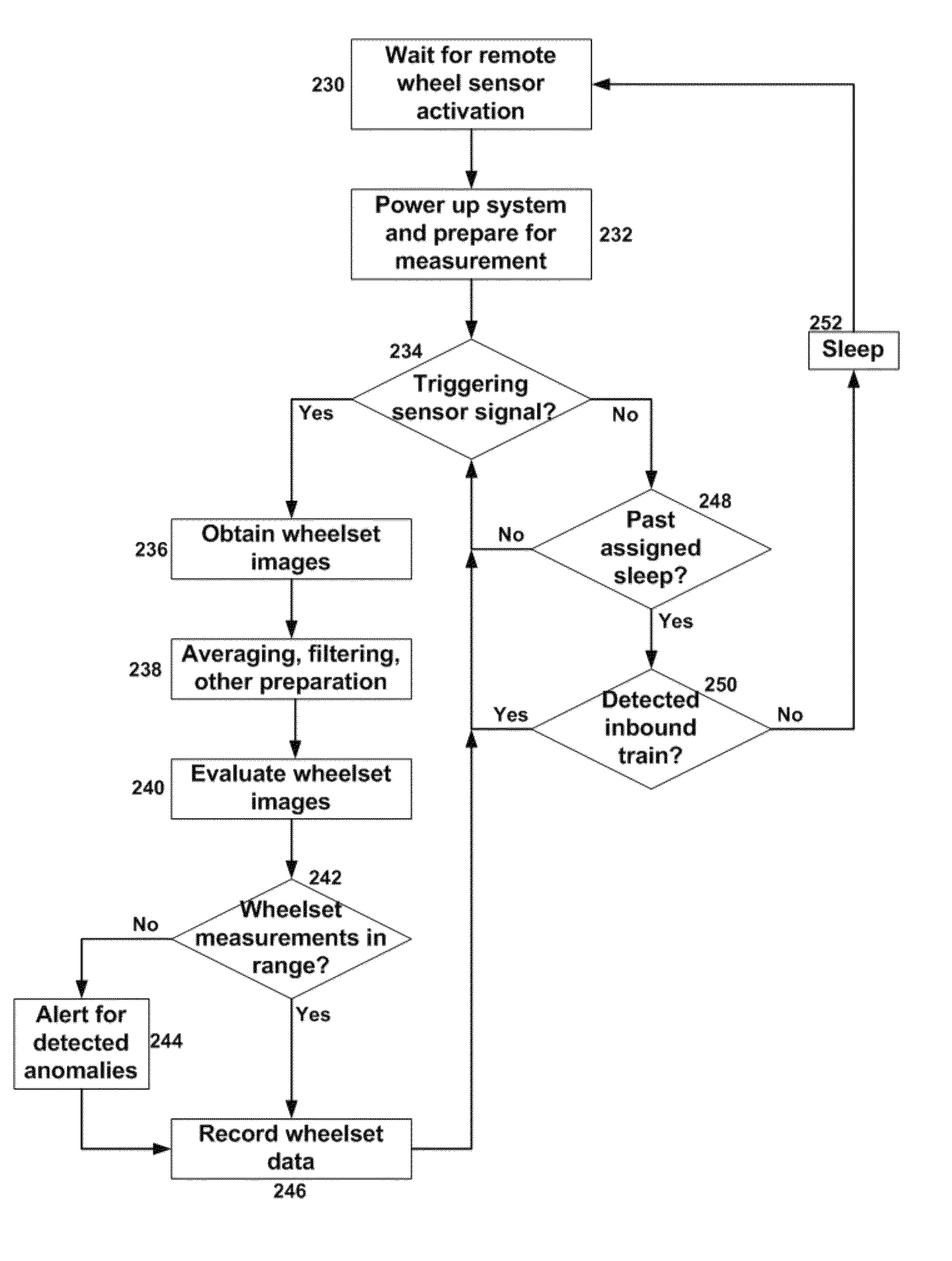
[0030]As indicated above, aspects of the invention provide a solution for identifying and quantifying geometric anomalies known to influence the service life of the rolling stock or the ride comfort for the case of passenger service. The solution comprises an optical system, which can be configured to accurately perform measurements at mainline speeds (e.g., greater than 100 mph). The optical system includes laser line projectors and imaging cameras and can utilize structured light triangulation. As used herein, unless otherwise noted, the term “set” means one or more (i.e., at least one) and the phrase “any solution” means any now known or later developed solution.

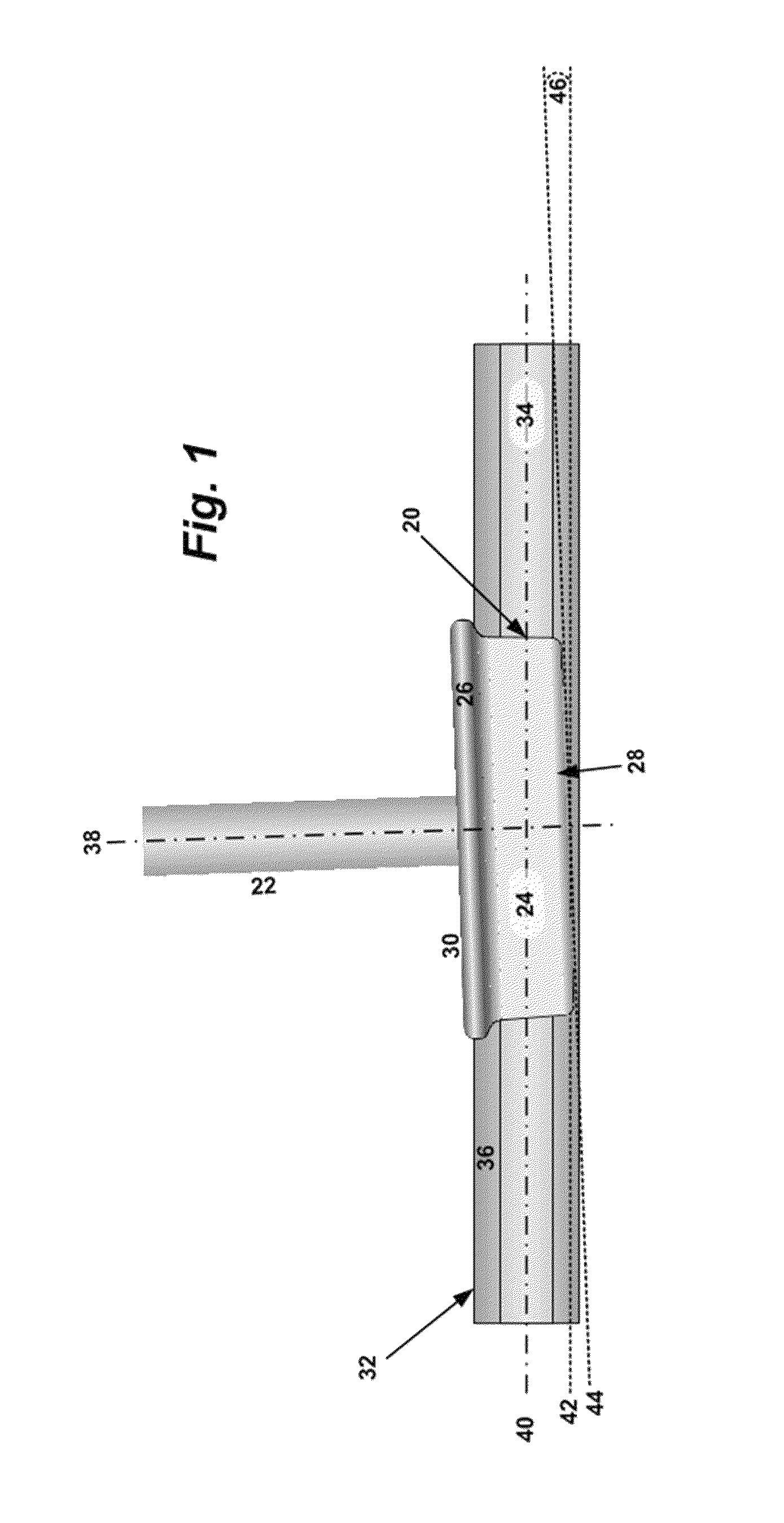
[0031]Turning to the drawings, FIG. 1 illustrates wheel to rail geometry showing the angle of attack. In FIG. 1, a wheel 20 is attached to an axle 22. The wheel 20 has key components including a tread 24, a flange 26, a field side 28 and a gauge side 30. The wheel 20 runs on its tread 24 on rail 32. The rail includes a ra...


PUM


Abstract

Considerable damage to rails, wheels, and trucks can result from geometric anomalies in the wheelsets, rails, and truck hardware. A solution for identifying and quantifying geometric anomalies known to influence the service life of the rolling stock or the ride comfort for the case of passenger service is described. The solution comprises an optical system, which can be configured to accurately perform measurements at mainline speeds (e.g., greater than 100 mph). The optical system includes laser line projectors and imaging cameras and can utilize structured light triangulation.

Description

REFERENCE TO PRIOR APPLICATIONS[0001]The current application claims the benefit of U.S. Provisional Application No. 61 / 688,910, titled “Method and Device for Wayside Measurement of Railcar Wheel to Rail Geometry,” which was filed on 24 May 2012, and which is hereby incorporated by reference.TECHNICAL FIELD[0002]This disclosure relates generally to the field of rail transportation, and more particularly, to determining a condition of a railcar wheelset and / or truck that may indicate an unsafe condition of the railcar wheelset and / or truck.BACKGROUND ART[0003]In railway service, rails are nominally parallel with a known elevation and a known cant with respect to a horizontal plane. Railcar wheelsets are mounted in pairs on a suspending device referred to as a truck (also called a bogie). Minimum wear on components and maximum ride comfort occurs when the wheelsets are centered on the rail with axes of rotation perpendicular to the rail centerline; any deviation from this alignment and...

Claims


Application Information

Patent Timeline
Patent Type & Authority Patents(United States)
IPC IPC(8): B61K1/00B61K9/12
CPCB61K9/12
Inventor GAMACHE, RONALD W.MIAN, ZAHID F.MULLANEY, JEREMY C.
Owner INT ELECTRONICS MACHINES
Why Eureka
Try Eureka