Method for improving connector enclosure adhesion

a technology of enclosure and connector, which is applied in the direction of coupling device details, coupling device connection, two-part coupling device, etc., can solve the problems of difficulty in adequately bonding the enclosure to the connector body, and achieve the effect of uniform distribution of bonding materials, small geometry and greater bond strength

Inactive Publication Date: 2015-01-06
APPLE INC
View PDF11 Cites 4 Cited by
  • Summary
  • Abstract
  • Description
  • Claims
  • Application Information

AI Technical Summary

Benefits of technology

[0007]The present invention relates to attaching enclosures to connector bodies having relatively small geometry. By way of example, the design may be used on data and / or power connectors, such as USB connectors, Firewire connectors, Thunderbolt connectors and the like. The design enables more uniform distribution of bonding material between a connector body and an outer enclosure, resulting in greater bond strength and a more reliable connector. This design is particularly useful when the geometry and clearances within the connector are so small that it is difficult to adequately bond the enclosure to the connector body.
[0010]In some embodiments, a bonding material may be deposited on the inside surface of an enclosure, before it is slid over the connector body. The bonding material may be substantially aligned with the entry of the bonding channels. The process of sliding the enclosure over the body may create pressure on the bonding material causing it to smear, or distribute, across the outside surface of the connector body, including the bonding channels. In some embodiments, the bonding channels may create a low resistance “preferred path” for distribution of the bonding material. In other embodiments the bonding material and or the geometry and the surface finish of the bonding channels may be designed to employ capillary wicking to improve the distribution of the bonding material within the bonding channels.

Problems solved by technology

This design is particularly useful when the geometry and clearances within the connector are so small that it is difficult to adequately bond the enclosure to the connector body.

Method used


Image

  • Method for improving connector enclosure adhesion
  • Method for improving connector enclosure adhesion
  • Method for improving connector enclosure adhesion

Examples


Embodiment Construction

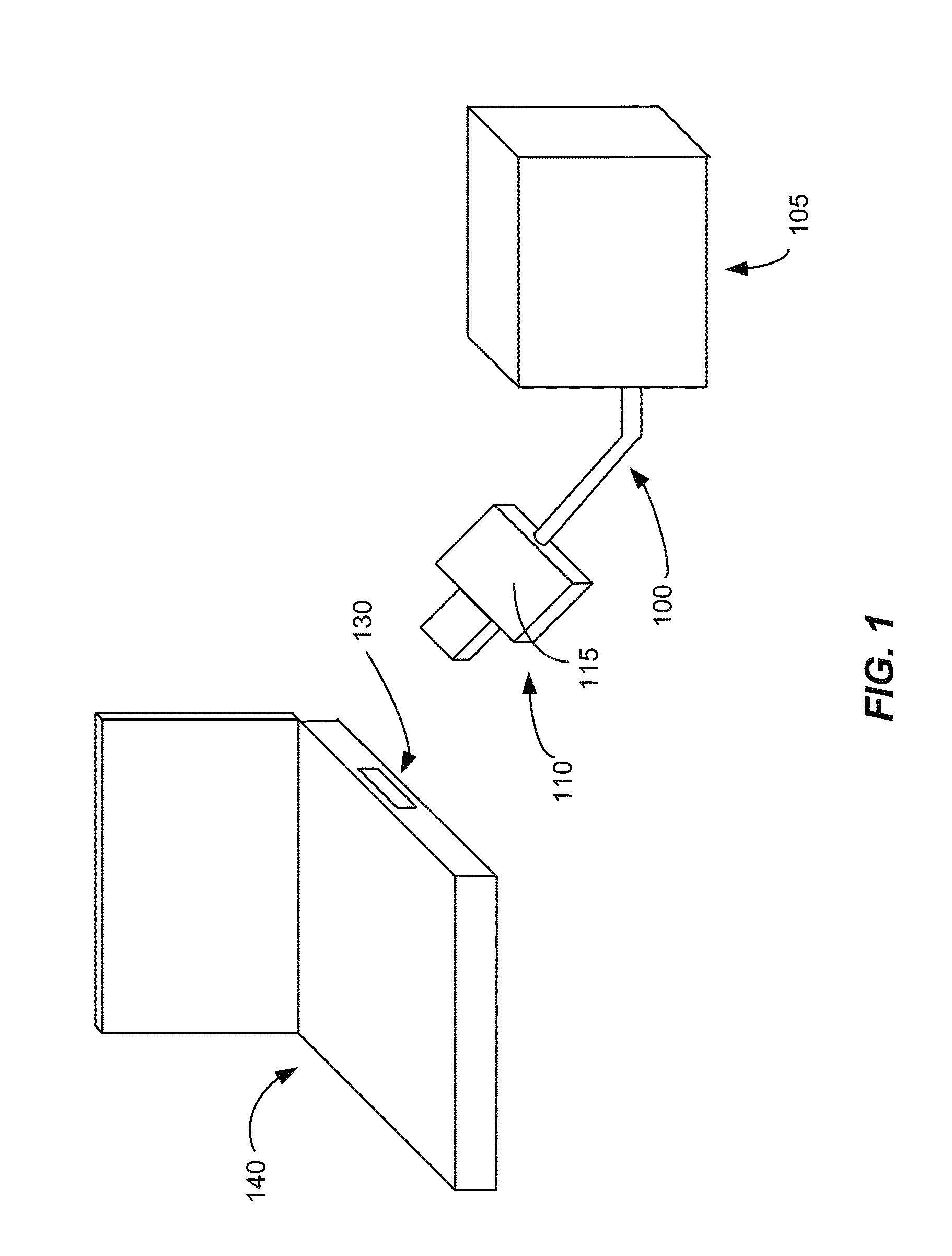
[0025]Many electronic devices such as smart-phones, media players, and tablet computers have connectors that facilitate battery charging and / or communication with other devices. The connectors include a plurality of electrical contacts through which electrical connections are made to another compatible connector to transfer power and / or data signals through the connectors. FIG. 1 illustrates an example of two such connectors including a plug connector 110 and a receptacle connector 130. Each of these connectors 110, 130 may comply with a well-known standard such as Universal Serial Bus (USB) 2.0, Firewire, Thunderbolt, or the like or may be proprietary connectors, such as the 30-pin connector used on many Apple products among other types of proprietary connectors.

[0026]As further shown in FIG. 1, plug connector 110 is coupled to a cable 100, which in turn is coupled to a peripheral device 105 that can be any of many different electronic devices or accessories that operate with such ...


PUM

PropertyMeasurementUnit
perimeteraaaaaaaaaa
depthaaaaaaaaaa
depthaaaaaaaaaa

Abstract

An improved method is employed to attach an enclosure to a connector body having relatively small geometry. One or more bonding channels are disposed in the outside surface of the connector body. During assembly of an enclosure over the connector body, a bonding material is distributed within the bonding channels and subsequently cured. The bonding channels and the bonding material are designed to employ capillary wicking to aid in the distribution of the bonding material within the bonding channels.

Description

[0001]This application claims the benefit under 35 USC §119(e) to U.S. Provisional Patent Application No. 61 / 693,163, filed Aug. 24, 2012.BACKGROUND OF THE INVENTION[0002]The present invention relates generally to electrical connectors and in particular to connectors having enclosures.[0003]A wide variety of electronic devices are available for consumers today. Many of these devices have connectors that that facilitate communication with and / or charging of the corresponding device. These connectors often interface with other connectors through cables that are used to connect devices to one another. Sometimes, connectors are used without a cable to directly connect the device to another device, such as a charging station or a sound system.[0004]As smart-phones, media players and other electronic devices become more compact, their corresponding connectors play a greater role in the ultimate market success of the device. For example, in many nano-scale MP3 players and compact flash sto...

Claims


Application Information

Patent Timeline
Patent Type & Authority Patents(United States)
IPC IPC(8): H01R11/30H01R13/46H01R13/504H01R24/60H01R43/00
CPCH01R13/46H01R43/00H01R13/504H01R24/60Y10T29/49208
Inventor SIAHAAN, EDWARDWEBB, MICHAEL
Owner APPLE INC
Why Eureka
Try Eureka