
Male connector, female connector and connector arrangement

a female connector and connector technology, applied in the direction of coupling contact members, coupling device connections, electric discharge lamps, etc., can solve the problems of easy damage, unwanted interference of the end of the contact, damage to the tip of the electrical contact, etc., and achieve the effect of more strength

Active Publication Date: 2015-01-06
KONINK PHILIPS ELECTRONICS NV
View PDF9 Cites 0 Cited by
  • Summary
  • Abstract
  • Description
  • Claims
  • Application Information

AI Technical Summary

Benefits of technology

The invention is about a connector that has good protection for the electrical contacts when connected to another connector. The design is also easy to use and is strong enough for heavy duty conditions. The male and female connectors have curved sections that improve the connection between them. The hook-like extensions on the connectors provide protection for the tips of the contacts and improve the overall connection. The female receiving portion strengthens the mechanical reception between the connectors. Overall, the invention provides a reliable and durable connector arrangement.

Problems solved by technology

This is especially the case with connectors for providing a data exchange connection, which may comprise a large number of electrical contacts that can easily be damaged when the different connector parts are plugged together.
Although the problem of establishing a reliable mechanical connection between the two connector bodies is satisfactory solved by this arrangement, there remains the problem of damaging the tips of the electrical contacts when the two connector parts are pushed together.
A small disalignment of the tips of the contacts can be enough to cause an unwanted interference of the ends of the contacts so that they are distorted or the like.
If one electrical contact of a first connector is damaged once, the damage can be spread by connecting this first connector to another connector, because the damaged contact can further damage other contacts in the respective complementary connector in another connector arrangement.

Method used


Image

  • Male connector, female connector and connector arrangement
  • Male connector, female connector and connector arrangement
  • Male connector, female connector and connector arrangement

Examples


Embodiment Construction

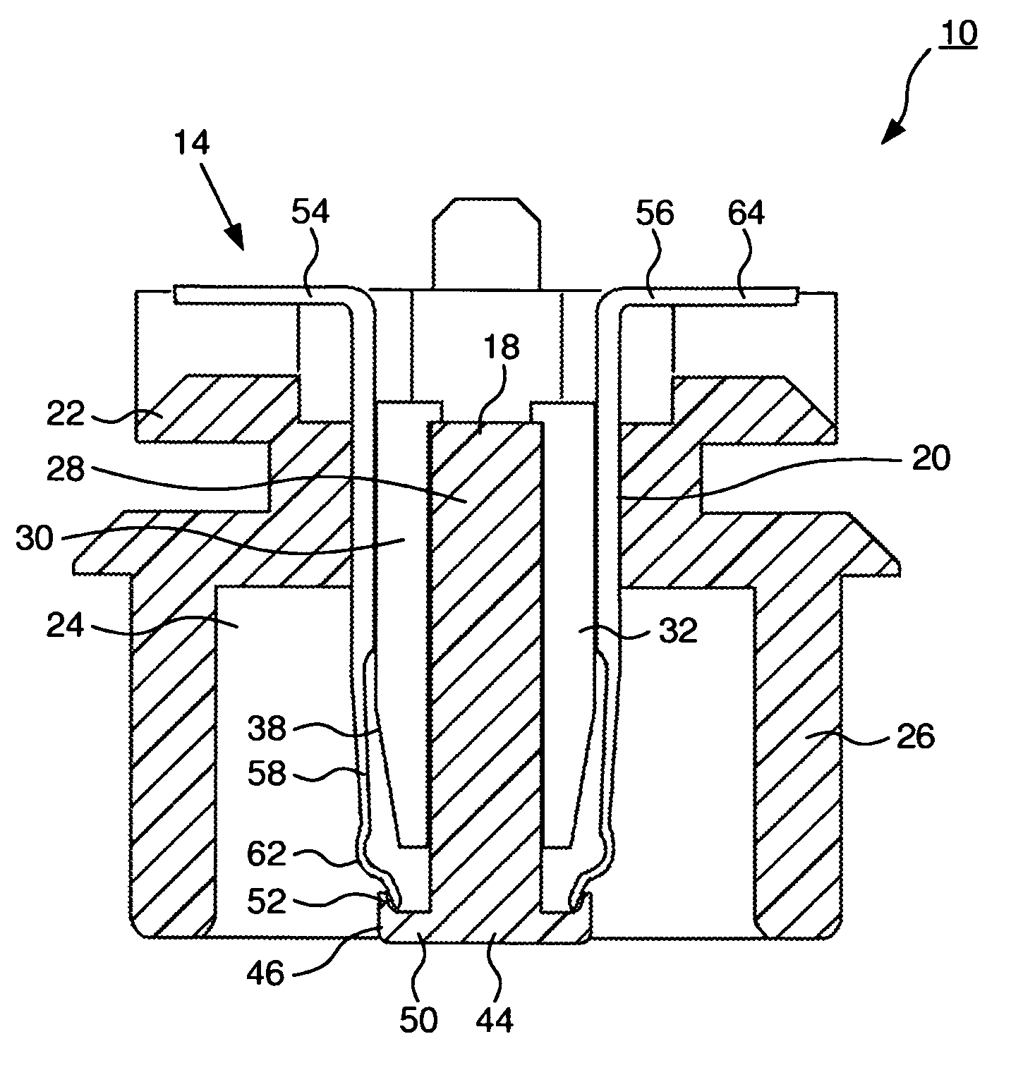
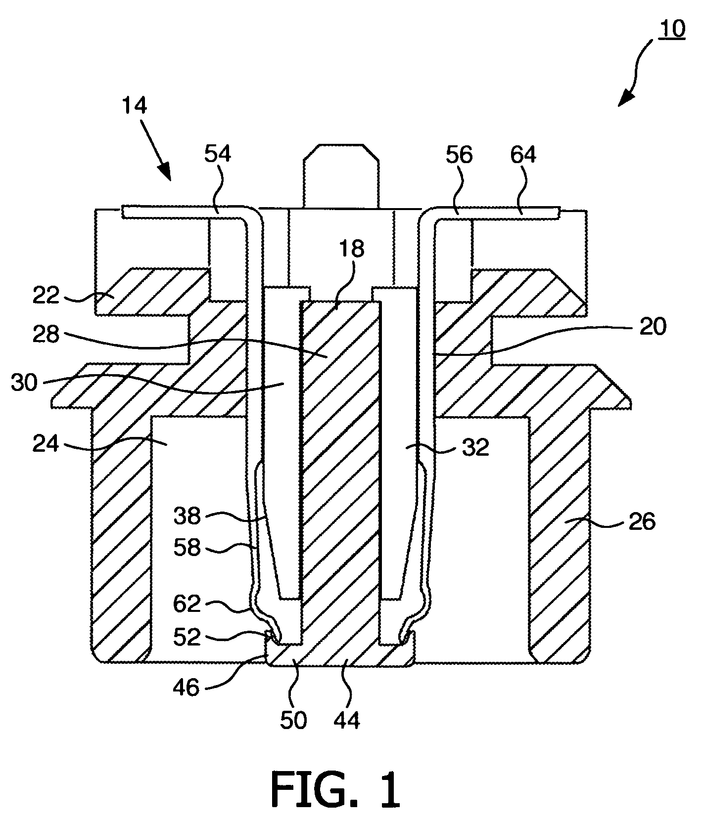
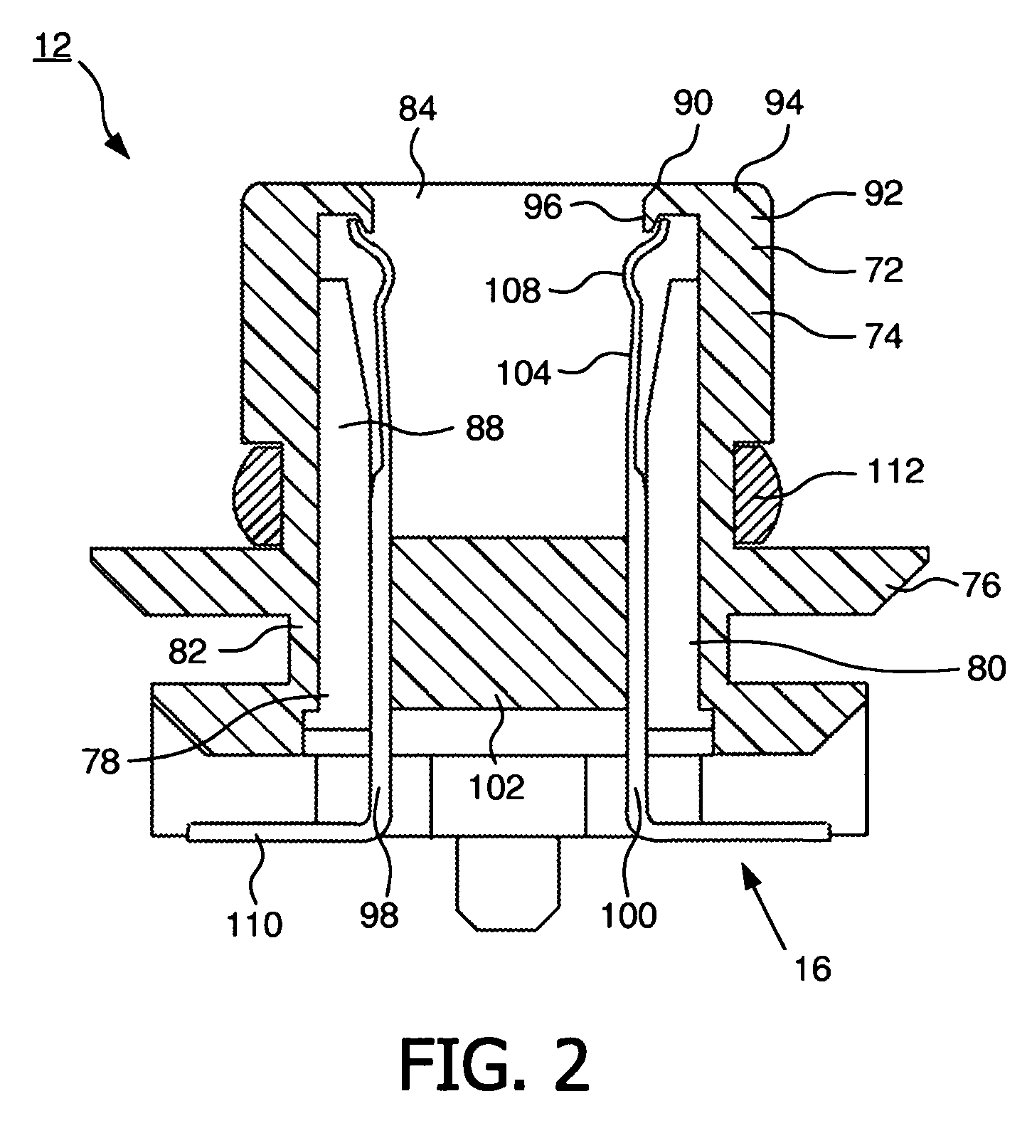
[0032]The connector arrangement according the present invention comprises a male connector 10 shown in FIG. 1 and a female connector 12 shown in FIG. 2. The male connector and the female connector 12 are connectable by pushing their respective connector bodies together so that electrical contacts comprised within the respective connector bodies engage with each other. In the present case the male connector 10 and the female connector 12 are provided as connectors of electric units for medical use. For example, the connector arrangement according to FIGS. 3 and 4 can be used to establish a data connection for data exchange between different electric stand-alone units.

[0033]In the following the male connector 10 shall be described with respect to FIG. 1. This male connector 10 comprises a connector body generally denoted by reference number 14 and being described as a first connector body 14 in the following. This first connector body 14 is provided to be inserted into a second connec...


PUM


Abstract

The male connector (10) comprises a first connector body (14) comprising electrical contacts (54, 56) extending towards the free insertion end (44) of the first connector body (14) and provided with free end portions (58) that are elastically deformable. The first connector body (14) comprises a plug portion (18) extending in the insertion direction and being provided with first hook-like extensions (46) at its free ends extending laterally outward. The hook-like extensions (46) cover the free end portions (58) of the electrical contacts (54, 56) of the first connector body (14) which are elastically biased outwardly to engage the first hook-like extensions (46). Moreover, the female connector (12) comprises a second connector body (16) with electric contacts (98, 100) extending towards the insertion end and being provided with free end portions (104) which are elastically deformable. The second connector body (16) comprises a socket portion (72) enclosing the electrical contacts (98, 100) and comprising the insertion opening, the edge (90) defining this opening being provided with further hook-like extensions (92) extending radially inward.

Description

FIELD OF THE INVENTION[0001]The invention relates to the field of connectors, especially to a male connector, a female connector and a connector arrangement comprising such a male connector and a female connector.BACKGROUND OF THE INVENTION[0002]Connectors are used in various applications for connecting electrical components to submit electrical energy or data between these components. Such connectors can be used to connect different electric apparatuses mutually as stand-alone units, to connect each of these stand-alone units with a power grid for power supply or to provide a connection between such units to form a network for data exchange.[0003]To provide a realiable electric connection even under heavy duty conditions, the electrical contacts may be comprised within a connector body that protects the damageable tips of the electrical contacts. This is especially the case with connectors for providing a data exchange connection, which may comprise a large number of electrical con...

Claims


Application Information

Patent Timeline
Patent Type & Authority Patents(United States)
IPC IPC(8): H01R24/00H01R12/00H01R12/70H01R13/44
CPCH01R13/44H01R12/7082H01R9/091H01R12/00
Inventor FLACHSLAENDER, ERWIN
Owner KONINK PHILIPS ELECTRONICS NV
Learn More