Support material removing method

a technology of supporting materials and removing methods, which is applied in the direction of process efficiency improvement, additive manufacturing, manufacturing tools, etc., can solve the problems of large-scale equipment and high cost, and achieve the effect of removing more quickly and reliably

Inactive Publication Date: 2015-01-06
MACOHO
View PDF17 Cites 9 Cited by
  • Summary
  • Abstract
  • Description
  • Claims
  • Application Information

AI Technical Summary

Benefits of technology

[0019]Since the present invention is designed as described above, the support material can be removed more quickly and reliably than with the conventional method previously described, and since there is no need for a chemical solution treatment, the present invention is a revolutionary support material removing method whereby a support material removal treatment can be performed easily, and other operational effects not seen in conventional practice are also achieved.

Problems solved by technology

However, the problems with this method are that the support material cannot be sufficiently removed (some slipperiness remains on the surface of the three-dimensional object), large-scale equipment is needed such as high-output pumps and pipes for wastewater treatments, and high costs are incurred.

Method used


Image

  • Support material removing method
  • Support material removing method
  • Support material removing method

Examples


examples

[0032]A specific example of the present invention is described based on the drawings.

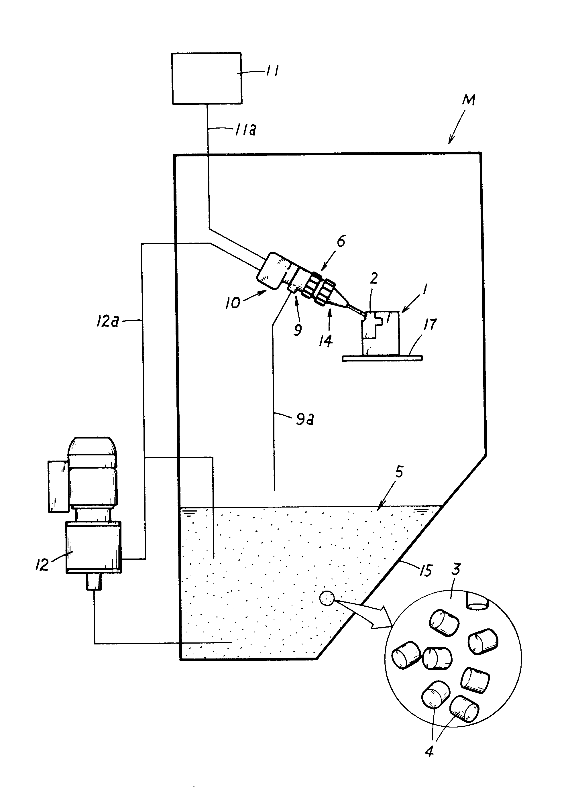
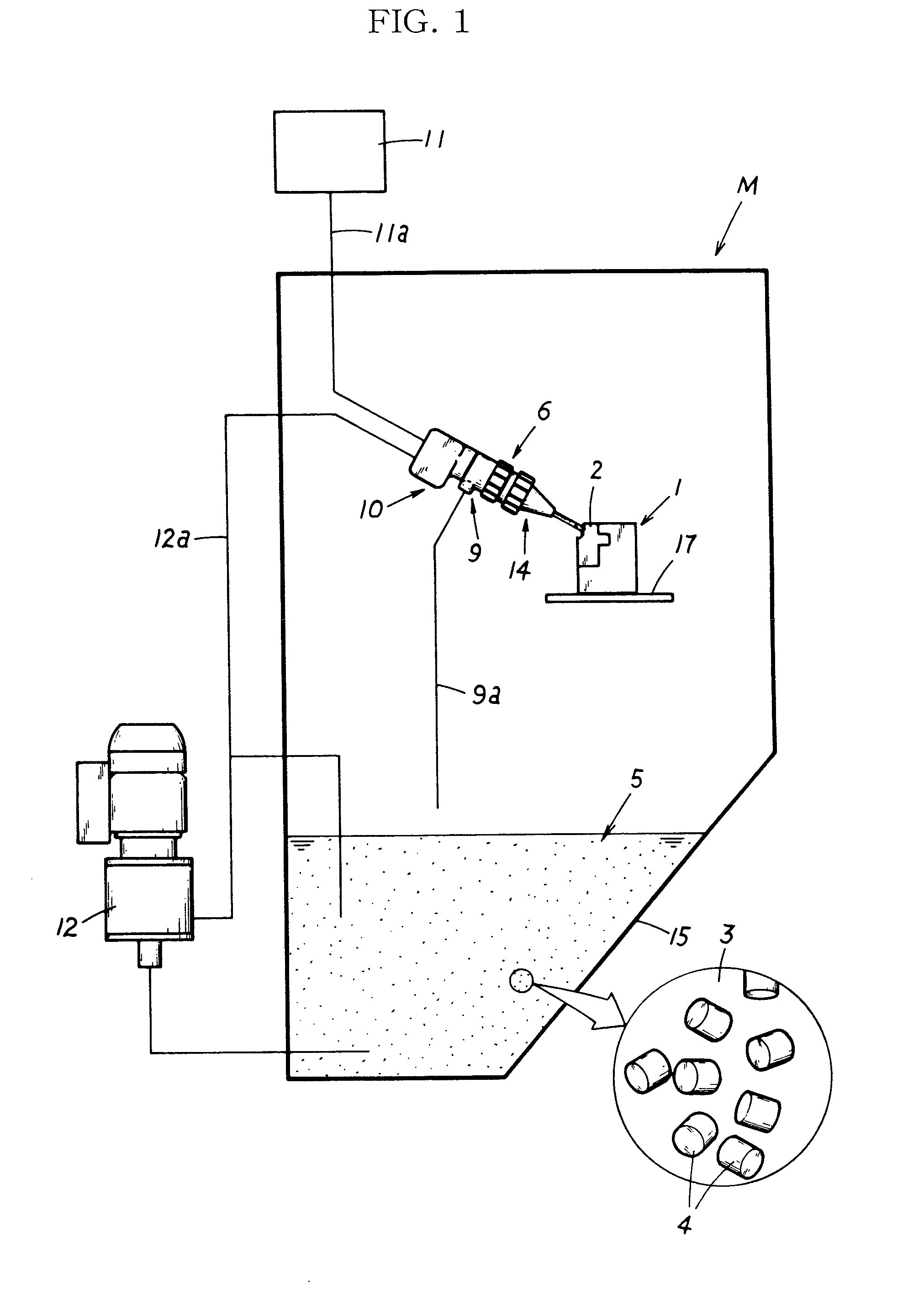
[0033]The present example is a method for removing a support material 2 located on the surface 1a of a three-dimensional object 1, and is performed using a surface treatment device M which sprays a slurry 5 which is a mixture of a liquid 3 and abrasive grains 4, described hereinafter. The three-dimensional object 1 used as the treated object that is treated in the present example is a three-dimensional object 1 made of a synthetic resin (an ultraviolet-cured resin) molded by a three-dimensional forming device (commonly known as a 3D printer), and an alkali-soluble support material 2 is formed as a layer over the surface 1a of the three-dimensional object 1.

[0034]Specifically, this surface treatment device M has a slurry sprayer 6 installed inside a case body 16 as shown in FIG. 1, a slurry reservoir 15 installed in a position underneath the slurry sprayer 6, a slurry supplier 12 for supplying the sl...


PUM

PropertyMeasurementUnit
heightaaaaaaaaaa
diameteraaaaaaaaaa
diameteraaaaaaaaaa

Abstract

An object of the present invention is to provide a revolutionary support material removing method which exhibits operational effects not seen in conventional practice.The present invention is a support material removing method for removing a support material (2) located on a surface (1a) of a three-dimensional object (1) molded by a three-dimensional forming device, wherein a slurry (5) which is a mixture of a liquid (3) and abrasive grains (4) is sprayed from a slurry sprayer (6) to remove the support material (2).

Description

TECHNICAL FIELD[0001]The present invention relates to a support material removing method for removing a support material on the surface of a three-dimensional object formed by a three-dimensional forming device.BACKGROUND ART[0002]In the past, there have been proposals of a three-dimensional forming device (commonly known as a 3D printer) which forms a three-dimensional object by an inkjet method, and a water jet method for removing by water-spraying pressure, for example, has commonly been used as the method for removing a support material on the surface of a three-dimensional object formed by this three-dimensional forming device. However, the problems with this method are that the support material cannot be sufficiently removed (some slipperiness remains on the surface of the three-dimensional object), large-scale equipment is needed such as high-output pumps and pipes for wastewater treatments, and high costs are incurred.[0003]In view of this, a method (hereinbelow the conventi...

Claims


Application Information

Patent Timeline
Patent Type & Authority Patents(United States)
IPC IPC(8): B24C1/08
CPCB24C1/00B24C1/04B24C1/086B24C7/0007B22F2998/00B29C64/112B29C64/40B29C64/35Y02P10/25B22F10/20B22F10/10B22F10/66
Inventor ASAI, YOSHIHISAOKURA, HIROSHITAKANO, SHINYA
Owner MACOHO
Why Eureka
Try Eureka