
Systems and methods for endometrial ablation

a technology of endometrial ablation and system, applied in the field of electrosurgical methods and devices, can solve the problems of perforation or other damage of the uterine cavity, and achieve the effect of minimizing the risk of disrupting the seal of the cervix

Active Publication Date: 2015-01-06
MINERVA SURGICAL
View PDF29 Cites 9 Cited by
  • Summary
  • Abstract
  • Description
  • Claims
  • Application Information

AI Technical Summary

Benefits of technology

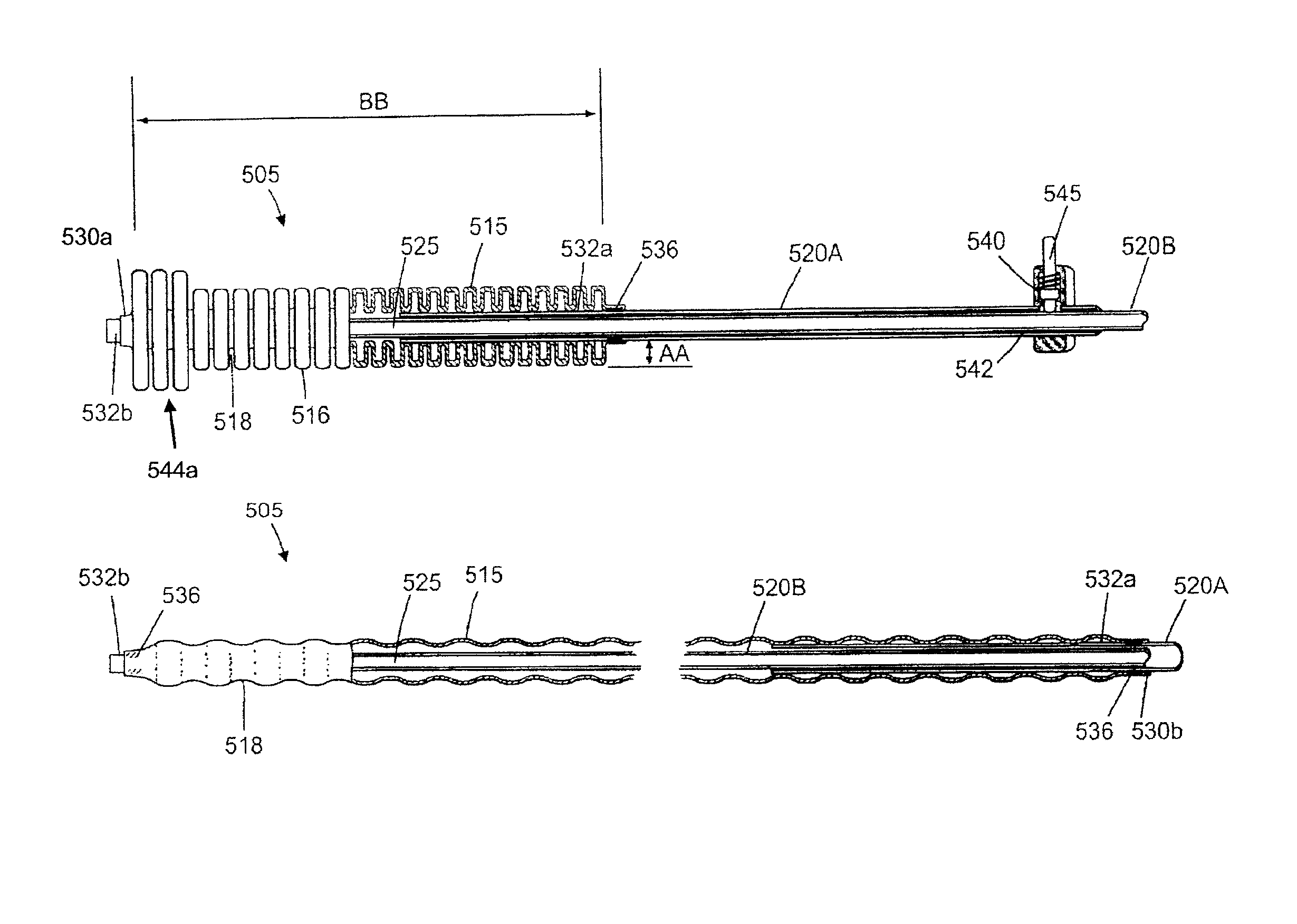
[0017]Systems according to the present invention for transcervical introduction to a patient's uterus comprise a radially expanding sleeve and a probe shaft. The radially expanding sleeve has a proximal end, a distal end, and a central passage between said ends. The sleeve is adapted to be introduced into the cervix or cervical canal in a reduced width configuration and to be immobilized within the cervical canal in an expanded width configuration. The probe shaft is slideably received in the central passage of the sleeve so that the shaft may be advanced, retracted, and otherwise manipulated within the central passage while the sleeve remains immobilized in the cervix or cervical canal, typically during a therapeutic or diagnostic procedure, more typically during a uterine ablation procedure. Such sealing of the cervix and / or cervical canal can inhibit and preferably prevent thermal or other damage from occurring during the procedure. Sealing the cervix and / or cervical canal with a sleeve that can remain immobilized during the procedure is particularly advantageous since it allows the therapeutic, diagnostic, or other device associated with the probe shaft to be repositioned and otherwise manipulated during the procedure while minimizing the risk of disturbing the protective seal. While prior devices have had seals affixed to the therapeutic device, such fixed seals are more likely to be dislodged during performance of the therapeutic and / or diagnostic procedure.
[0020]The present invention further provides methods for accessing a patient's uterus. The methods comprise immobilizing a sleeve in the patient's cervix or cervical canal where the sleeve has a central passage. A probe shaft is repositioned within the central passage while the sleeve remains immobilized, thus allowing the physician to position or reposition a diagnostic or therapeutic tool on the shaft within the uterus while minimizing the risk of disrupting the seal to the cervix. The sleeve may be initially introduced to the cervical canal while the probe is present in the central passage or, alternatively, the sleeve may be positioned without the sleeve being present. In the latter case, the sleeve will be advanced through the probe after the seal has been immobilized. Both cases, the sleeve is typically immobilized by radially expanding a wall or exterior portion of the sleeve within the cervical canal. Expansion of the sleeve may be achieved by causing or allowing the sleeve to axially foreshorten and / or by inflating at least a portion of the wall of the sleeve. Optionally, distal balloon may be inflated or otherwise expanded within the uterine cavity at the distal end of the sleeve. Optionally, the sleeve and the probe shaft may be selectively locked to each other this so that the immobilized sleeve may stabilize the position of a therapeutic or a diagnostic tool on the probe shaft within the uterus. Typically, locking is accomplished by actuating a locking mechanism on the sleeve, usually on a proximal collar of the sleeve which remains accessible to the treating physician during the procedure.

Problems solved by technology

The uterine cavity may be perforated or otherwise damaged by the transcervical introduction of probes and instruments into the uterine cavity.

Method used


Image

  • Systems and methods for endometrial ablation
  • Systems and methods for endometrial ablation
  • Systems and methods for endometrial ablation

Examples


Embodiment Construction

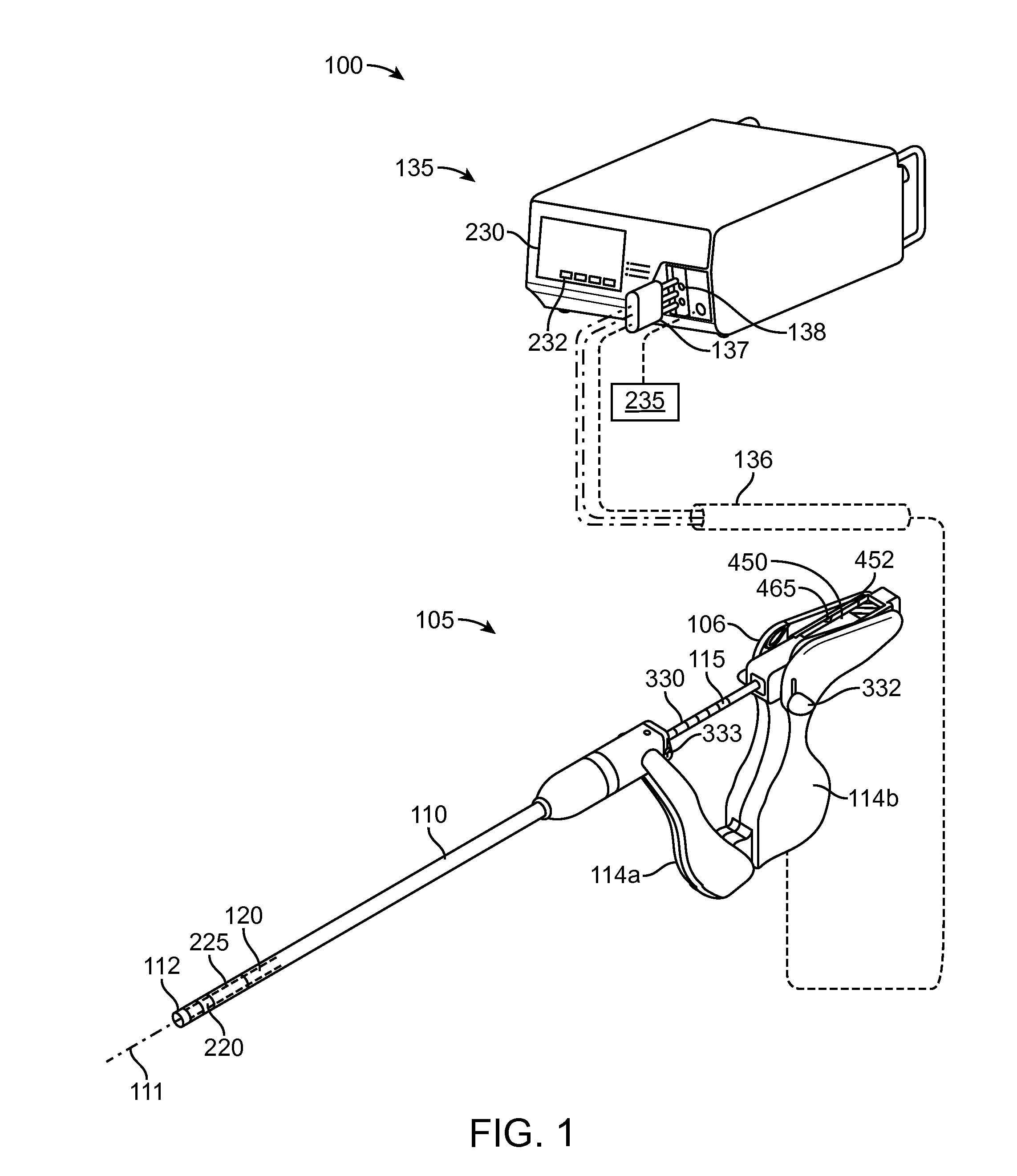
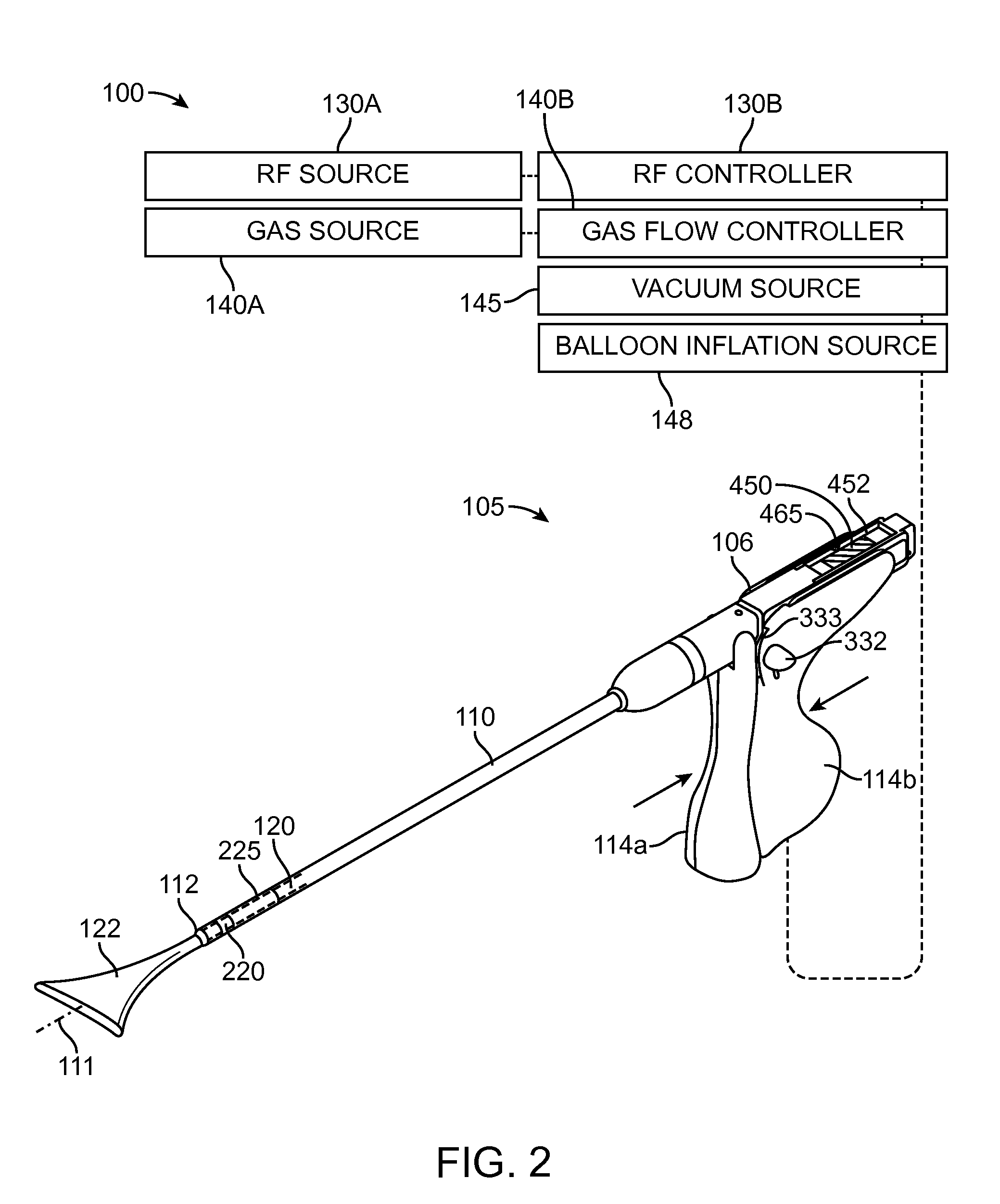
[0051]In general, an electrosurgical ablation system is described herein that comprises an elongated introducer member for accessing a patient's uterine cavity with a working end that deploys an expandable thin-walled dielectric structure containing an electrically non-conductive gas as a dielectric. In one embodiment, an interior chamber of the thin-walled dielectric structure contains a circulating neutral gas such as argon. An RF power source provides current that is coupled to the neutral gas flow by a first polarity electrode disposed within the interior chamber and a second polarity electrode at an exterior of the working end. The gas flow, which is converted to a conductive plasma by an electrode arrangement, functions as a switching mechanism that permits current flow to engaged endometrial tissue only when the voltage across the combination of the gas, the thin-walled dielectric structure and the engaged tissue reaches a threshold that causes capacitive coupling across the ...


PUM


Abstract

A system for treating uterine tissue having a seal assembly configured for positioning in a patient's cervical canal and uterine cavity; an expandable distal balloon portion; an expandable elongate medial balloon portion configured for movement between a first transversely expanded shape for engaging a cervical canal and a second transversely non-expanded shape for trans-cervical insertion; and a fluid source in communication with distal balloon portion and medial balloon portion for expansion of said balloon portions.

Description

CROSS-REFERENCE TO RELATED APPLICATIONS[0001]This application claims the benefit of Provisional Application No. 61 / 393,776, filed on Oct. 15, 2010, the full disclosure of which is incorporated herein by reference.[0002]This application is related to but does not claim priority from application Ser. No. 12 / 711,506, filed on Feb. 24, 2010, and Ser. No. 13 / 094,715, filed on Apr. 26, 2011, the full disclosures of which are incorporated herein by reference.BACKGROUND[0003]1. Field of the Invention[0004]The present invention relates to electrosurgical methods and devices for global endometrial ablation in a treatment of menorrhagia. More particularly, the present invention relates to applying radiofrequency current to endometrial tissue by means of capacitively coupling the current through an expandable, thin-walled dielectric member enclosing an ionized gas.[0005]A variety of devices have been developed or proposed for endometrial ablation. Of relevance to the present invention, a variet...

Claims


Application Information

Patent Timeline
Patent Type & Authority Patents(United States)
IPC IPC(8): A61B17/42A61B17/46A61D1/10A61B18/00A61B18/14
CPCA61B17/42A61B18/1485A61B2017/4225A61B2018/00232A61B2018/00559A61B2018/00577A61B18/042A61B2018/00285A61B2018/00791A61B2018/00863A61B2018/122A61B2090/064A61B2218/007A61B2017/00199A61B2017/00132A61B2017/00017A61B2017/00137A61B2018/147A61B2018/0063A61B18/1206A61B18/14A61B2018/0022
Inventor TRUCKAI, CSABA
Owner MINERVA SURGICAL
Learn More