Electromagnetic switch for starter

a technology of electromagnetic switch and starter, which is applied in the direction of magnets, relays, magnetic bodies, etc., can solve the problems of moisture that has intruded into the contact compartment and freezes to the contact surface, and the contact surface may have conduction defects, so as to prevent the increase of sliding resistance, increase the attractive force of the solenoid, and minimize intrusion.

Inactive Publication Date: 2015-01-06
DENSO CORP
View PDF5 Cites 12 Cited by
  • Summary
  • Abstract
  • Description
  • Claims
  • Application Information

AI Technical Summary

Benefits of technology

[0012]With this configuration, whether the solenoid is in its active or inactive state, the outer circumferential periphery of the slidable member is entirely circumferentially in sliding contact with the inner circumferential periphery of the cylindrical bore. That is, the slidable member and the cylindrical bore overlap each other in the radial direction. As such, there is substantially no clearance between the outer circumferential periphery of the slidable member and the inner circumferential periphery of the cylindrical bore, which provides hermeticity between the plunger compartment (an inner space of the solenoid in which the plunger is axially movable) and the contact compartment. This can minimize intrusion of moisture from the plunger compartment into the contact compartment. Hence, even if a little moisture that has intruded from the plunger compartment into the contact compartment freezes to contact faces of the fixed contacts and / or the movable contact, a film of ice will not grow. This allows a breaking force required to break the ice on the contact faces of the fixed contacts and / or the movable contact to be reduced. It is therefore unnecessary to increase an attractive force of the solenoid required to break the ice on the contact faces of the fixed contacts and / or the movable contact.
[0013]In the electromagnetic switch as configured above, the presence of sliding contact portions of the outer circumferential periphery of the plunger and the outer circumferential periphery of the slidable member may cause the plunger and the slidable member to be off-center from each other when the solenoid is in its active state. To this, the slidable member is configured to be a separate member from the plunger and loosely encompass the outer circumferential periphery of the plunger rod. Hence, even when the plunger and the slidable member are off-center from each other, the slidable member is radially movable with radial play. This can prevent prying of the plunger and the plunger rod due to the plunger and the slidable member being off-center from each other, thereby preventing increase of sliding resistance.
[0014]Since attractive forces of the solenoid can be reduced as compared to the electromagnetic switch as disclosed in Japanese Patent Application Laid-Open Publication No. 2006-177160, the outer diameter of the solenoid is allowed to be reduced, which leads to reduction of both size and weight of the electromagnetic switch.

Problems solved by technology

In the above configuration, however, a spatial gap between the inner diameter of the cylindrical bore in the fixed iron core and the outer diameter of the plunger rod may lead to fluid communication between a plunger movement space in which the plunger can axially move (hereinafter referred to as a plunger compartment) and the contact compartment, so that moisture is prone to intrude from the plunger compartment into the contact compartment.
Hence, for example, when the outside temperature falls below freezing, the moisture that has intruded into the contact compartment may freeze to contact surfaces of the fixed contacts and / or the movable contact.
This may lead to conduction defects between these contacts during operation of the electromagnetic switch.
This, however, gives rise to a disadvantage that the outer diameter of the electromagnetic switch will be increased.

Method used


Image

  • Electromagnetic switch for starter
  • Electromagnetic switch for starter
  • Electromagnetic switch for starter

Examples


first embodiment

[0021]There will now be explained a starter including an electromagnetic switch in accordance with one embodiment of the present invention.

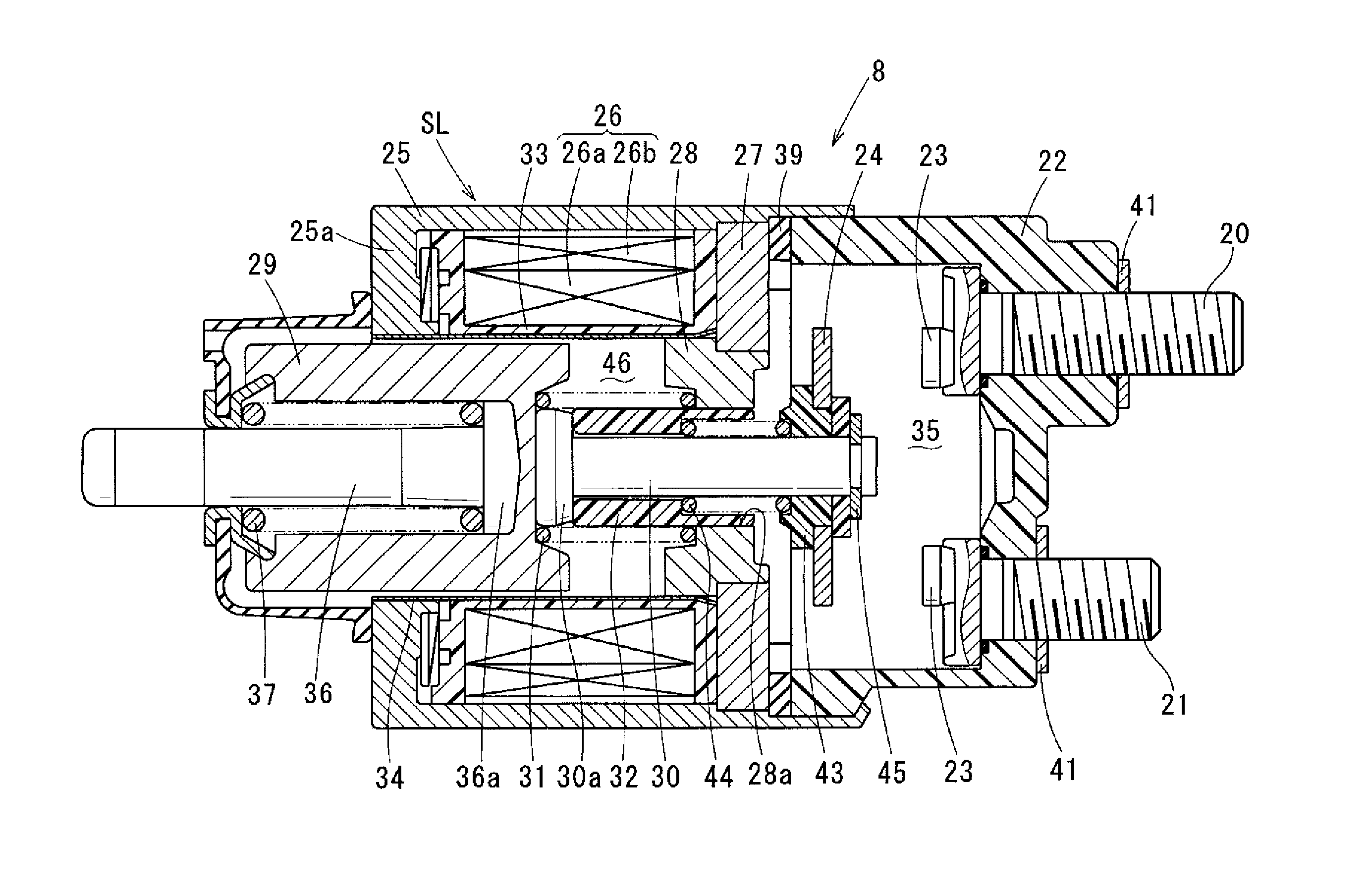
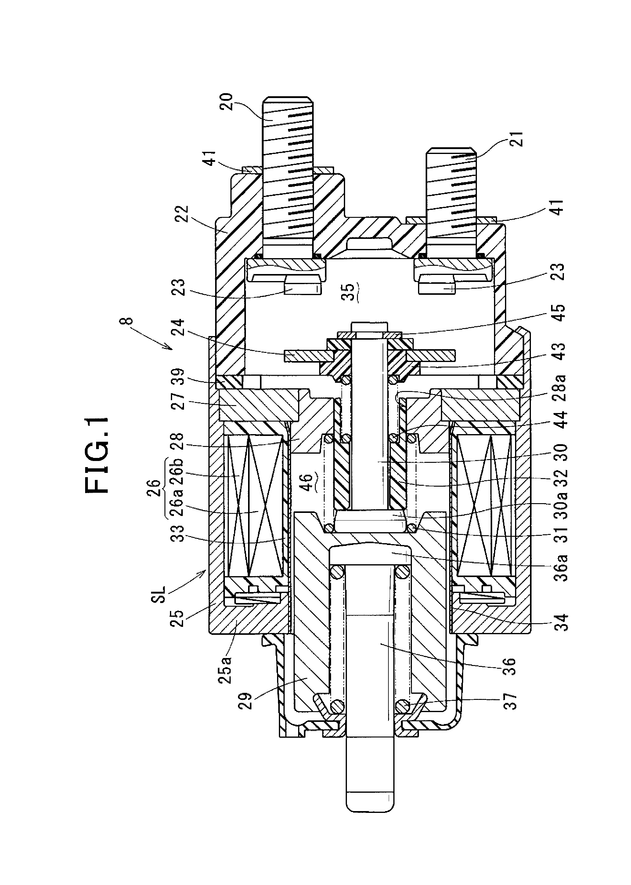
[0022]The starter 1, as shown in FIG. 4, includes a motor 2 that receives supplied power to generate a torque, a speed reducer 3 that reduces a rotation speed of the motor 2, a shock absorber (described later) that absorbs excessive shock transmitted from an engine, an output shaft 4 to which the generated torque is transferred from the motor 2 via the speed reducer 3, a pinion 6 disposed along the output shaft 4 integrally with a clutch 5, an electromagnetic switch 8 that drives a shift lever 7 to push the pinion 6 in the anti-plunger direction (to the left as viewed in FIG. 4) and opens and closes a main contact (described later) to thereby interrupt energization current to the motor 2, and a housing 9 in which the motor 2 and the electromagnetic switch 8 are mounted.

[0023]The motor 2 is a direct-current (DC) commutator motor including a magnet...


PUM

PropertyMeasurementUnit
energization currentaaaaaaaaaa
inner diameteraaaaaaaaaa
diameteraaaaaaaaaa

Abstract

An electromagnetic switch for a starter. The electromagnetic switch includes a cylindrical slidable member that is separate from a plunger, loosely encompasses an outer circumferential periphery of a plunger rod, and is axially movable integrally with the plunger. Whether the solenoid is in its active or inactive state, the slidable member is at least partially axially inserted into an inner circumferential periphery of a cylindrical bore and an outer circumferential periphery of the slidable member is entirely circumferentially in sliding contact with the inner circumferential periphery of the cylindrical bore.

Description

CROSS-REFERENCE TO RELATED APPLICATION[0001]This application is based on and claims the benefit of priority from earlier Japanese Patent Applications No. 2012-276540 filed Dec. 19, 2012, the descriptions of which are incorporated herein by reference.BACKGROUND[0002]1. Technical Field[0003]The present invention relates to a starter electromagnetic switch for opening and closing a main contact provided on a starter motor circuit to thereby switch on and off motor energization current.[0004]2. Related Art[0005]A known starter electromagnetic switch, as disclosed in Japanese Patent Application Laid-Open Publication No. 2006-177160, includes a solenoid configured to form an electromagnet through energization of a coil to drive a plunger by means of an attractive force of the electromagnet, and a movable contact attached to an end of a plunger rod secured to the plunger. The movable contact is arranged in opposition to a pair of fixed contacts electrically connected to a starter motor cir...

Claims


Application Information

Patent Timeline
Patent Type & Authority Patents(United States)
IPC IPC(8): H01H67/02H01F7/13H01H9/04H01H50/02H01H51/06
CPCH01H50/023H01H51/065H01H9/041
Inventor HIRABAYASHI, TAKASHI
Owner DENSO CORP
Why Eureka
Try Eureka