

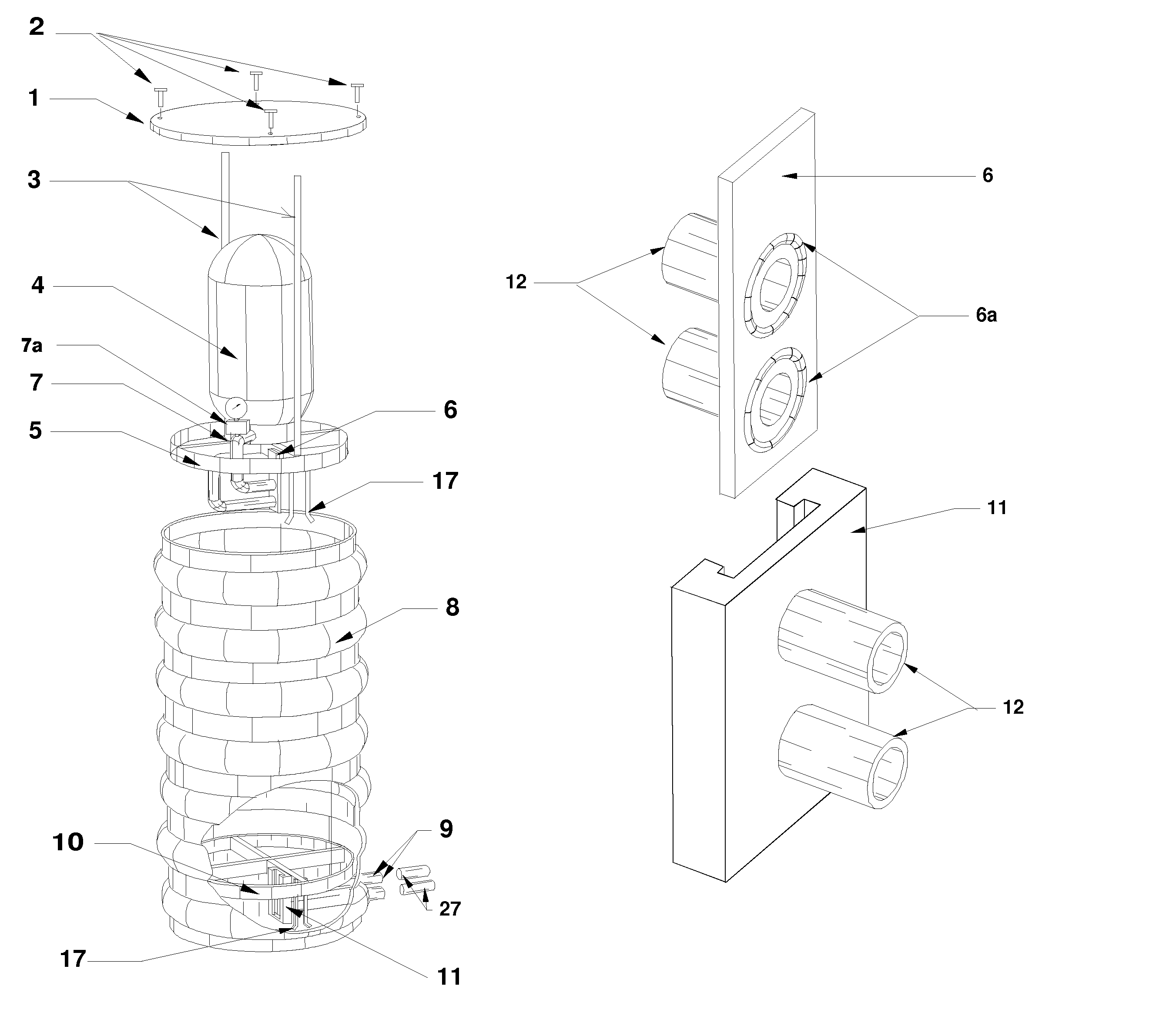
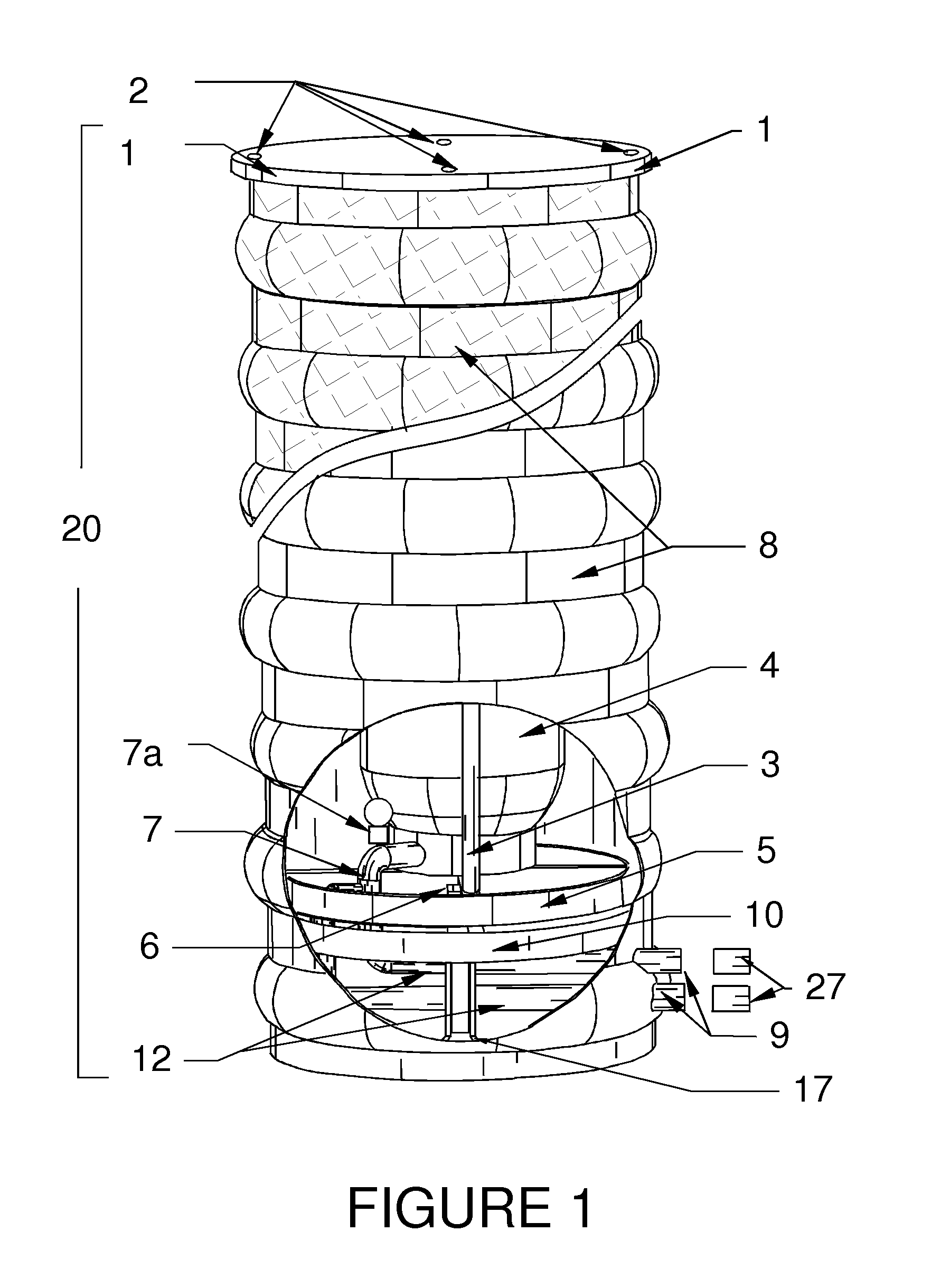
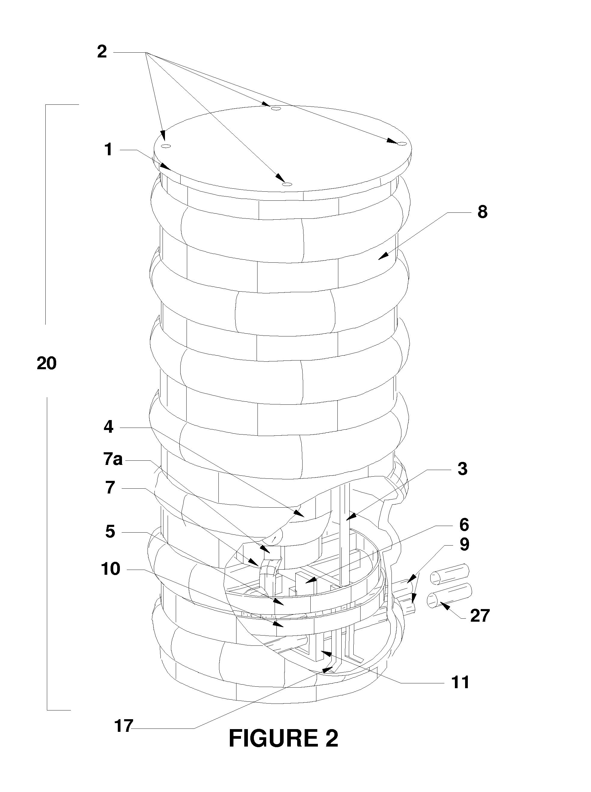
Device for containment, protection and easy installation and removal of a liquid handling system
a technology for liquid handling systems and containment devices, applied in the field of water systems, can solve the problems of liquid handling systems occupying valuable building space, defective or worn-out devices of fluid pumping devices installed in homes or other buildings, and causing extensive damage to the device, so as to minimize the intrusion of environmental elements, minimize distortion, and minimize the effect of distortion of the housing
- Summary
- Abstract
- Description
- Claims
- Application Information
AI Technical Summary
Benefits of technology
Problems solved by technology
Method used
Image

Examples
Embodiment Construction
[0019]Embodiments of the invention are discussed below with reference to the Figures. However, those skilled in the art will readily appreciate that the detailed description given here with respect to these figures is for explanatory purposes as the invention extends beyond these limited embodiments. For example, without limitation, it should be appreciated that those skilled in the art will, in light of the teachings of the present invention, recognize a multiplicity of alternate and suitable approaches, depending on the needs of the particular application, to implement the functionality of any given detail described herein, beyond the particular implementation choices in the following embodiments described and shown. That is, there are numerous modifications and variations of the invention that are too numerous to be listed but that all fit within the scope of the invention. Also, singular words should be read as plural and vice versa and masculine as feminine and vice versa, wher...
PUM
 Abstract
Description
Claims
Application Information