Crimp tool for crimping pin and socket contacts

a crimping tool and pin technology, applied in forging/pressing/hammering apparatus, semiconductor/solid-state device testing/measurement, instruments, etc., can solve problems such as aluminum wire corrosion, and achieve the effect of preventing the oxidation of the wire attached and minimizing the intrusion of moistur

Active Publication Date: 2007-01-16
DANIELS MFG CORP
View PDF20 Cites 11 Cited by
  • Summary
  • Abstract
  • Description
  • Claims
  • Application Information

AI Technical Summary

Benefits of technology

[0005]The present invention is directed to a new form of indenter for crimping an open end of a connector pin about an insulation covered wire in order to minimize intrusion of moisture into the pin to prevent oxidation of the wire attached to the pin. In one form, the invention comprises a compound indenter having a first indenter section for crimping an outer open end of the connection pin about the insulation and a second indenter section for crimping or indenting the pin so as to connect the pin to a metallic wire. In an illustrative example, the first indenter section utilizes a pair of opposed indenter elements having facing flat anvil surfaces and a second pair of opposed indenter elements having facing arcuate anvil surfaces. The first pair of flat surfaces are driven into contact with the open end of the pin to cause the open end to first deform into a generally oval configuration. Subsequently, the second pair of indenter elements having arcuate surfaces are driven into contact with the open end of the pin in a direction normal to the plane of the first pair of flat surfaces. The arcuate anvil surfaces compress the open end of the pin into a generally circular configuration while the flat surfaces prevent the open end of the pin from expanding outwardly during the compression cycle. The dual action of the two sets of indenter elements thus deform the open end of the pin into a generally circular configuration which fits tightly about the insulation covered wire inserted into the pin.

Problems solved by technology

One problem that exists with aluminum wire conductors is that exposure of the conductor to moisture may result in corrosion of the aluminum wire.

Method used


Image

  • Crimp tool for crimping pin and socket contacts
  • Crimp tool for crimping pin and socket contacts
  • Crimp tool for crimping pin and socket contacts

Examples


Embodiment Construction

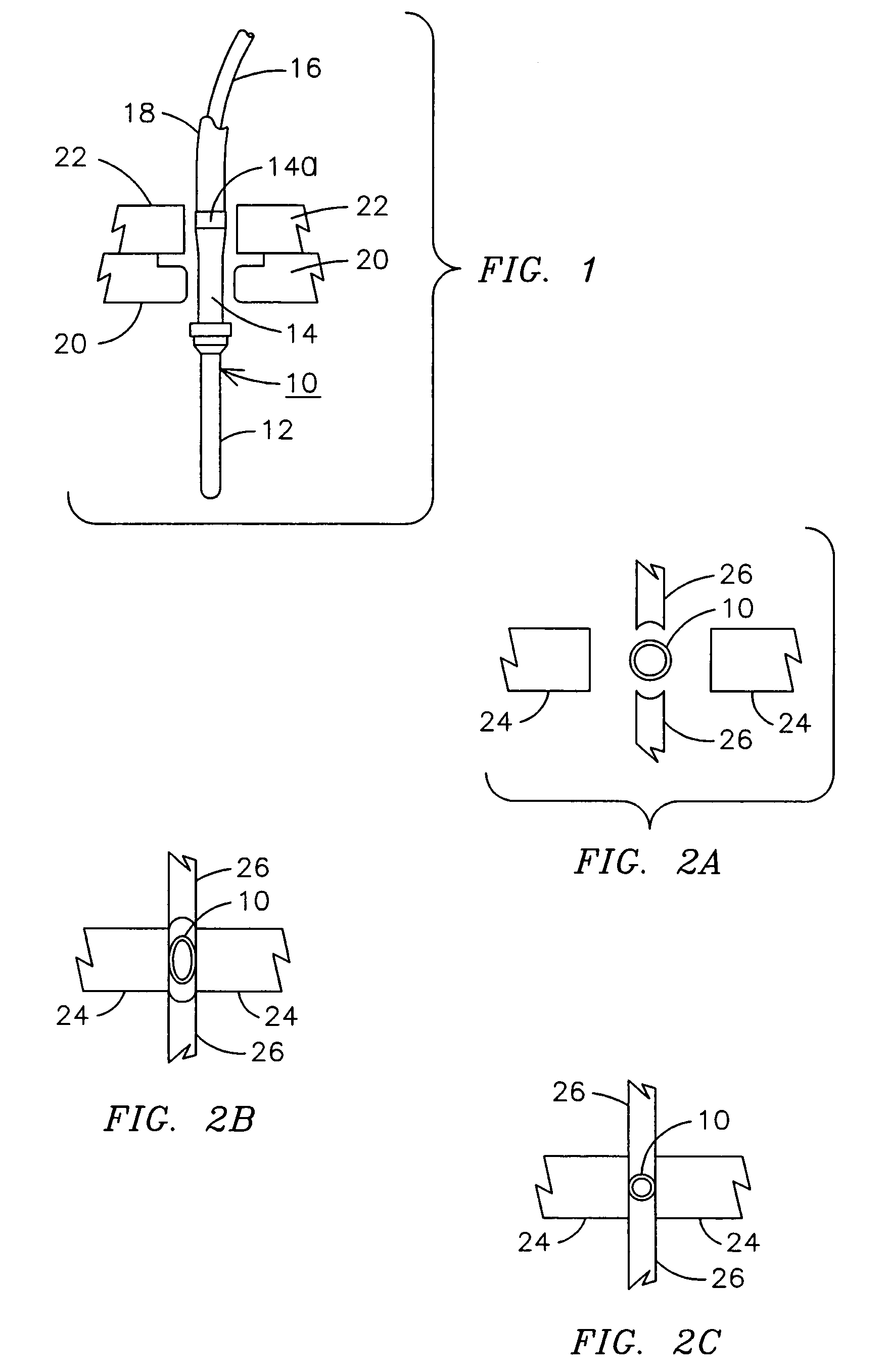
[0013]FIG. 1 illustrates a design of one form of connector pin 10 (sometimes referred to as a contact) having a contact tip 12 and a hollow portion 14 for receiving a nickel-plated aluminum conductor 16 from which insulation has been stripped and for receiving a length of conductor from which the insulation material 18 surrounding the conductor 16 has not been stripped. As can be seen, the open end 14a of the pin portion 14 has a larger diameter opening to allow the insulation material 18 to be inserted at least partially within the portion 14. FIG. 1 also shows the position of a first indenter 20 which is designed to crimp the pin 10 in a conventional manner so as to capture and hold the conductor 16 within the hollow portion 14. Positioned adjacent the portion 14a of the pin 10 is a second indenter 22 which is designed to crimp the portion 14a about the insulation 18 on the conductor 16. The indenter 22 is uniquely designed to assure that all sides of the portion 14a tightly encom...


PUM

PropertyMeasurementUnit
degree anglesaaaaaaaaaa
axial lengthaaaaaaaaaa
lengthaaaaaaaaaa

Abstract

A compound indenter for a wire connector pin, the pin having an axial length and an opening at an end thereof for receiving a wire having an exposed portion and an insulation covered portion, the opening being sized to receive both the exposed portion and a length of the insulation covered portion comprises a first indenter having a plurality of indenting elements for engaging the pin in an axial location overlaying the exposed portion of the wire inserted in the pin and a second indenter having a plurality of indenting elements for engaging the pin in an axial location overlaying the insulation covered portion of the wire inserted in the pin. The apparatus advances the indenting elements of each of the first and second indenters generally concurrently for compressing respective sections of the pin into engagement with the exposed wire portion and the insulation covered portions of the wire.

Description

SPECIFIC DATA RELATED TO THE INVENTION[0001]This application claims the benefit of U.S. provisional application No. 60 / 406,520, filed Aug. 28, 2002 and U.S. provisional application No. 60 / 448,043 filed Feb. 20, 2003.BACKGROUND OF THE INVENTION[0002]The present invention relates to a crimping tool for pin and socket contacts and more particularly, to a tool for crimping a pin at two separate distinct locations in which the pin has a different diameter at each location.[0003]Connectors used for aircraft applications generally comply with military specifications (mil spec) standards which require waterproof connectors that utilize a plurality of male and female pins in opposite ends of a mating connector pair to complete electrical connections between wire leads or conductors connected to the connector pair. Typically, the pins are small diameter elements that are replaceable in each of the mating connector pairs. A typical male pin has an end portion that is generally solid and a rear...

Claims


Application Information

Patent Timeline
Patent Type & Authority Patents(United States)
IPC IPC(8): H01R43/042
CPCH01R43/0424H01R43/0427Y10T29/53226
Inventor KELLY, WILLIAM D.MOO-YOUNG, AMOS A.
Owner DANIELS MFG CORP
Why Eureka
Try Eureka