
Battery box floor for electric vehicles and corresponding vehicle body

a battery box and electric vehicle technology, applied in the direction of batteries, cell components, electrochemical generators, etc., can solve problems such as cooling problems, and achieve the effects of improving crash performance, improving protection of battery box floors, and convenient manufacturing

Active Publication Date: 2020-06-11
AUTOTECH ENG SL
View PDF0 Cites 5 Cited by
  • Summary
  • Abstract
  • Description
  • Claims
  • Application Information

AI Technical Summary

Benefits of technology

The invention is a battery box floor for electric vehicles that is designed to reinforce the vehicle body, improve crash performance, and regulate cooling of the batteries independently from environmental conditions. It achieves these purposes by incorporating a deformation inner cavity between the lower cooling channels and the underbody protection, which prevents damage to the battery box floor and battery percussion during crashes. The inner cavity also provides improved cooling performance by providing stability to the cooling fluid temperature regardless of environmental conditions. The battery box floor is easy to manufacture. Overall, the invention ensures better safety and regulation of electric vehicles' battery box floor.

Problems solved by technology

The range of temperatures of an electrical vehicle in use can easily vary, e.g. between 60° C. and −30° C. this, especially in the case of the highest temperatures can lead to cooling problems.

Method used


Image

  • Battery box floor for electric vehicles and corresponding vehicle body
  • Battery box floor for electric vehicles and corresponding vehicle body
  • Battery box floor for electric vehicles and corresponding vehicle body

Examples


second embodiment

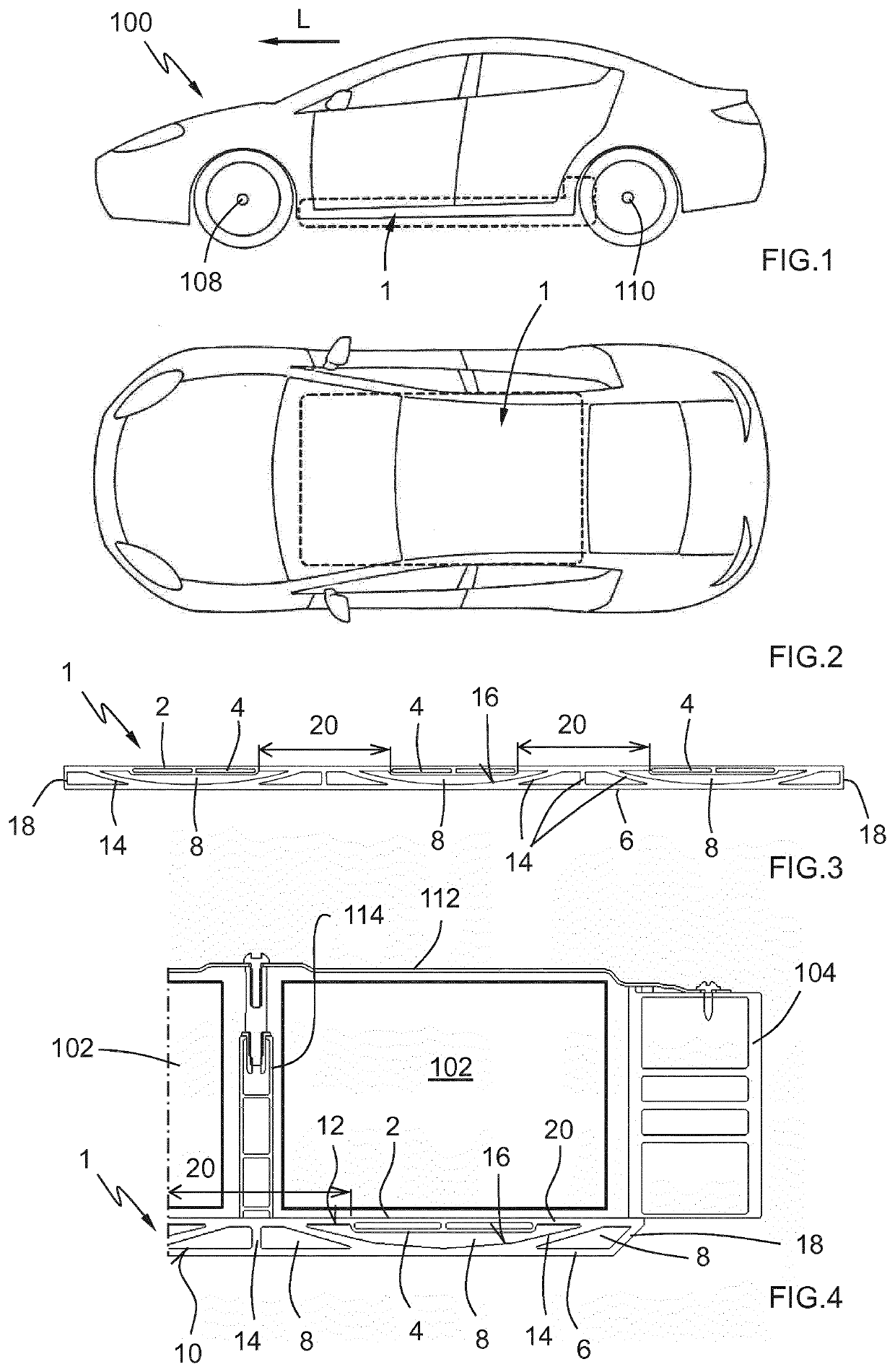
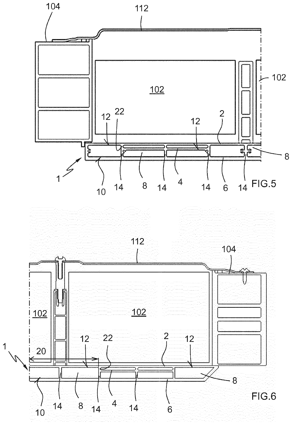
[0055]In the embodiment of FIG. 3, the outer walls 18 are perpendicular to both the battery pack supporting panel 2 and the underbody protection 6. Instead, in the embodiment of FIG. 4, these outer walls 18 form an angle relative to both the battery pack supporting panel 2 and the underbody protection 6. This second embodiment further improves the side crash behaviour in cases were the impact hits directly on these outer walls 18, because thanks to this chamfer like outer walls 18 the intensity of the normal impact force is reduced.

[0056]It is also relevant indicating, that in order to simplify the manufacturing process, the battery box floor is integrally formed from a metallic material. The metallic material is an aluminium alloy. Furthermore, the battery box floor is made up of at least one extruded part of said aluminium alloy.

[0057]As it is apparent, this extruded part forms the supporting panel 2, the lower cooling channels 4, the deformation inner cavity 8 and the underbody p...

sixth embodiment

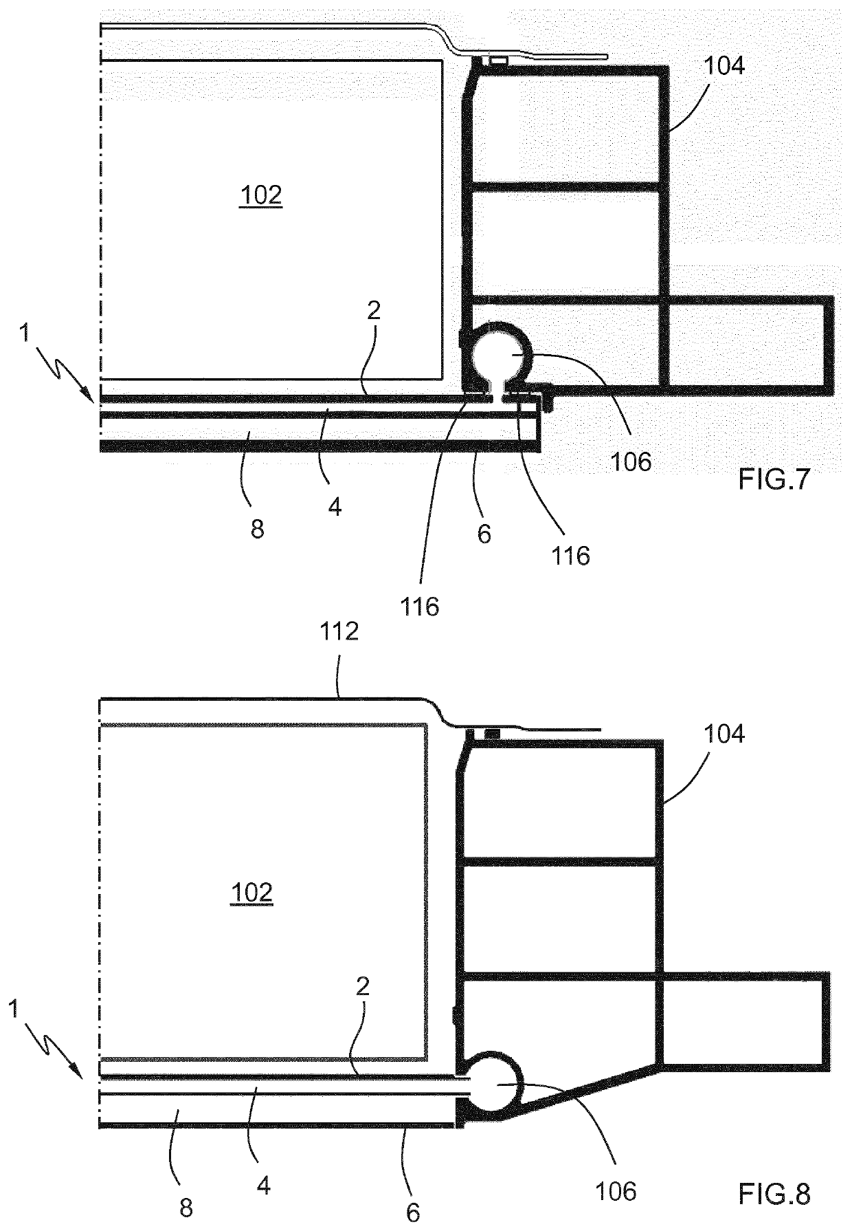
[0069]Finally, FIG. 8 shows the battery box floor 1 of the invention. In this case, differently to the embodiment of FIG. 7, the side beam cooling channel 106 is centred with the lower cooling channel 4 for making the circulation of cooling fluid much easier.

[0070]As it is apparent for the skilled person, the features of the different embodiments described herein can also be combined in several different ways.


PUM


Abstract

A battery box floor for electric vehicles for being arranged at the lower part of a vehicle body is disclosed. The battery box floor comprises a battery pack supporting panel for supporting a plurality of battery cells, a plurality of lower cooling channels for containing a cooling fluid, a plurality of lower cooling channels being arranged adjacent to and below the battery pack supporting panel such that they can cool the battery cells and an underbody protection arranged below the lower cooling channels. The battery box floor further comprises a deformation inner cavity between said plurality of lower cooling channels and said underbody protection. Additionally, the battery box floor is integrally formed from a metallic material. Also a vehicle body comprising the battery box floor is disclosed.

Description

DESCRIPTIONField of the Invention[0001]The invention relates to a battery box floor for electric vehicles for being arranged at the lower part of a vehicle body, said battery box floor comprising: a battery pack supporting panel for supporting a plurality of battery cells, a plurality of lower cooling channels for containing a cooling fluid, said plurality of lower cooling channels being arranged adjacent to and below said battery pack supporting panel such that they can cool said battery cells and an underbody protection arranged below said plurality of lower cooling channels.[0002]The invention relates also to a vehicle body comprising a battery box floor according to the invention.Definitions[0003]In the present invention the terms “cell”, “battery” or “battery cell” can be used interchangeably and refer to any type of battery used as an energy accumulation device for, among others, powering the corresponding motor of an electrical vehicle. This kind of batteries is, e.g. lithium...

Claims


Application Information

Patent Timeline
IPC IPC(8): B60K1/04B60K11/02H01M10/625H01M10/6556H01M2/10H01M50/204H01M50/224
CPCB60K2001/0438H01M2/1083B60K2001/005B60K1/04H01M2220/20H01M10/6556H01M10/625B60K11/02H01M10/653H01M50/204H01M50/224Y02E60/10
Inventor MARQUEZ DURAN, SERGIOVALERA AGEA, ALBERTORUIZ, CARLOSFARÍA RODRIGUEZ, SERGIO
Owner AUTOTECH ENG SL
Learn More