
Vertical flow wet-type electric precipitator and wet electric precipitation method

A wet electrostatic precipitator and vertical flow technology, applied in chemical instruments and methods, separation methods, dispersed particle separation, etc., can solve the problems of increasing the risk of system operation, difficulty in construction and maintenance, and increase in layout costs, and achieve enhanced Flue gas turbulence, ultra-low air leakage rate, and the effect of promoting micro-mixing

Active Publication Date: 2014-12-10
SHANGHAI LONGKING ENVIRONMENTAL PROTECTION
View PDF6 Cites 11 Cited by
  • Summary
  • Abstract
  • Description
  • Claims
  • Application Information

AI Technical Summary

Problems solved by technology

[0006] When the wet electrostatic precipitator and the desulfurization tower are integrated, there are disadvantages such as high tower body, difficult construction and maintenance, etc., and there may be mutual influence between the desulfurization section and the wet electric section. The desulfurization tower must also be shut down at the same time, and the desulfurization tower must also be shut down when there is a problem with the wet electrostatic precipitator, which increases the risk of system operation to a certain extent; The tower diameter of the front-end desulfurization tower is too large or too small. Due to the air leakage rate, complex structure and load problems of the wet electrostatic precipitator in the top-mounted tower, the integrated layout of the same tower increases the cost and even makes it difficult to arrange.
At the same time, there is still room for improvement in the flue gas treatment capacity and the removal efficiency of fine particles in the existing wet electrostatic precipitator

Method used


Image

  • Vertical flow wet-type electric precipitator and wet electric precipitation method
  • Vertical flow wet-type electric precipitator and wet electric precipitation method
  • Vertical flow wet-type electric precipitator and wet electric precipitation method

Examples


Embodiment Construction

[0047] In order to more clearly illustrate the technical solutions in the embodiments of the present invention or the prior art, the following will briefly introduce the drawings that need to be used in the description of the embodiments or the prior art. Obviously, the accompanying drawings in the following description are only These are some embodiments of the present invention. Those skilled in the art can also obtain other drawings based on these drawings without creative work.

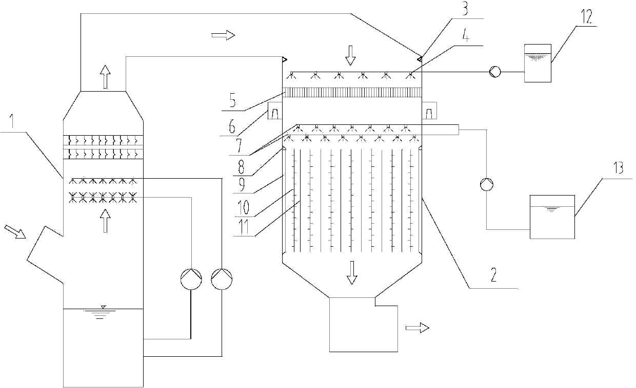
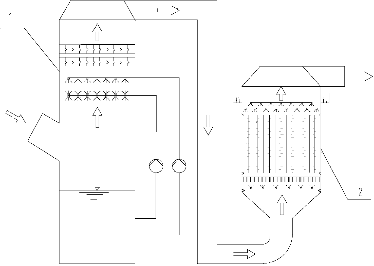
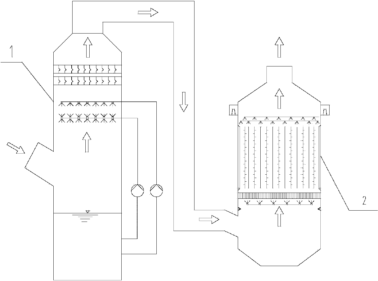
[0048] In Embodiment 1 of the present invention, refer to figure 1 , the vertical flow wet electrostatic precipitator 2 is set outside the desulfurization tower 1, and is located downstream of the desulfurization tower 1, the flue gas to be treated flows out from the flue gas outlet of the desulfurization tower 1 and then enters the vertical flow wet electrostatic precipitator 2, and the flue gas Gas flows vertically inside the electrostatic precipitator.

[0049] Among them, the vertical flow we...


PUM


Abstract

The invention provides a vertical flow wet-type electric precipitator and wet electric precipitation method. The vertical flow wet-type electric precipitator comprises an annular plate, a spray humidifying layer, a flue gas uniform distribution device, a dust removing electric field area, washing and spraying layers, a plurality of insulator boxes, an atomization water tank and a process water tank, wherein the spray humidifying layer comprises a fine atomizing nozzle and a spray pipeline; flue gas sequentially passes through the annular plate, the spray humidifying layer and the flue gas uniform distribution device; the dust removing electric field area is used for blocking a baffle board of a flue gas blind area; the washing and spraying layers are arranged above the dust removing electric field area; the wet electric precipitation method comprises the following steps: a continuous manner is adopted to conduct atomization and humidification on inlet flue gas and conduct uniformly distributed optimization treatment on the flue gas; an intermittent or continuous manner is adopted to conduct sprinkling and cleaning on a dust-collecting electrode and a discharge electrode; a method of hot air sweeping is adopted to ensure insulation. The vertical flow wet-type electric precipitator and the wet electric precipitation method can effectively ensure the high-efficient and stable operation of the vertical flow wet-type electric precipitator, optimize the fluid field, and strengthen turbulence and atomization of the flue gas; local micro-mixing, and collision as well as crash coagulation of fine particles are promoted; the dust removal efficiency is improved.

Description

technical field [0001] The invention relates to the technical field of flue gas treatment methods, in particular to a vertical flow wet electrostatic precipitator and a wet electrostatic precipitator. Background technique [0002] my country's coal-based energy structure will not change for a long time. So far, the basic methods of pollutant control in thermal power plants in my country mainly include: low-nitrogen combustion + SCR denitrification + dry dust removal + wet desulfurization. The existing control methods have low capture efficiency for PM2. For GGH units, the phenomenon of "gypsum rain" or "blue / yellow smoke" often appears at the chimney outlet, causing secondary pollution to the environment. [0003] In order to solve these problems, under the current conditions of my country's electric power environmental protection, it is necessary to adopt the deep purification technology of smoke and dust to improve the efficiency of dust removal, so as to effectively remov...

Claims


Application Information

Patent Timeline
Patent Type & Authority Applications(China)
IPC IPC(8): B01D50/00
Inventor 高继贤张小娟洪小松阎冬陈泽民
Owner SHANGHAI LONGKING ENVIRONMENTAL PROTECTION
Learn More