
Electric wire connecting method

a technology of connecting wires and wires, which is applied in the direction of connecting contact material, soldering apparatus, manufacturing tools, etc., can solve the problems of increasing production costs, complicated connecting work, and inability to acquire existing sleeves

Inactive Publication Date: 2015-01-13
YAZAKI CORP
View PDF31 Cites 18 Cited by
  • Summary
  • Abstract
  • Description
  • Claims
  • Application Information

AI Technical Summary

Benefits of technology

This patent describes a way to connect two electric wires together using a conductor and a stranded wire with multiple strands. The conductor is formed into a plate-like shape by pressing it and then the strands are welded onto the plate using ultrasonic welding. This method ensures a secure and reliable connection between the wires. The conductor can also be pressed together with the strands and the plate using a die during the welding process. The overall effect of this patent is to provide an efficient and effective way to connect electric wires.

Problems solved by technology

When these electric wires are connected tighter by a sleeve, there is a situation in which an existing sleeve cannot be appropriated.
Because of this, various types of sleeves need to be prepared according to diameters of electric wires to be connected, and this calls for complicated connecting work and increased production costs.

Method used


Image

  • Electric wire connecting method
  • Electric wire connecting method
  • Electric wire connecting method

Examples


Embodiment Construction

[0032]Hereinafter, an embodiment of the invention will be described by reference to the drawings.

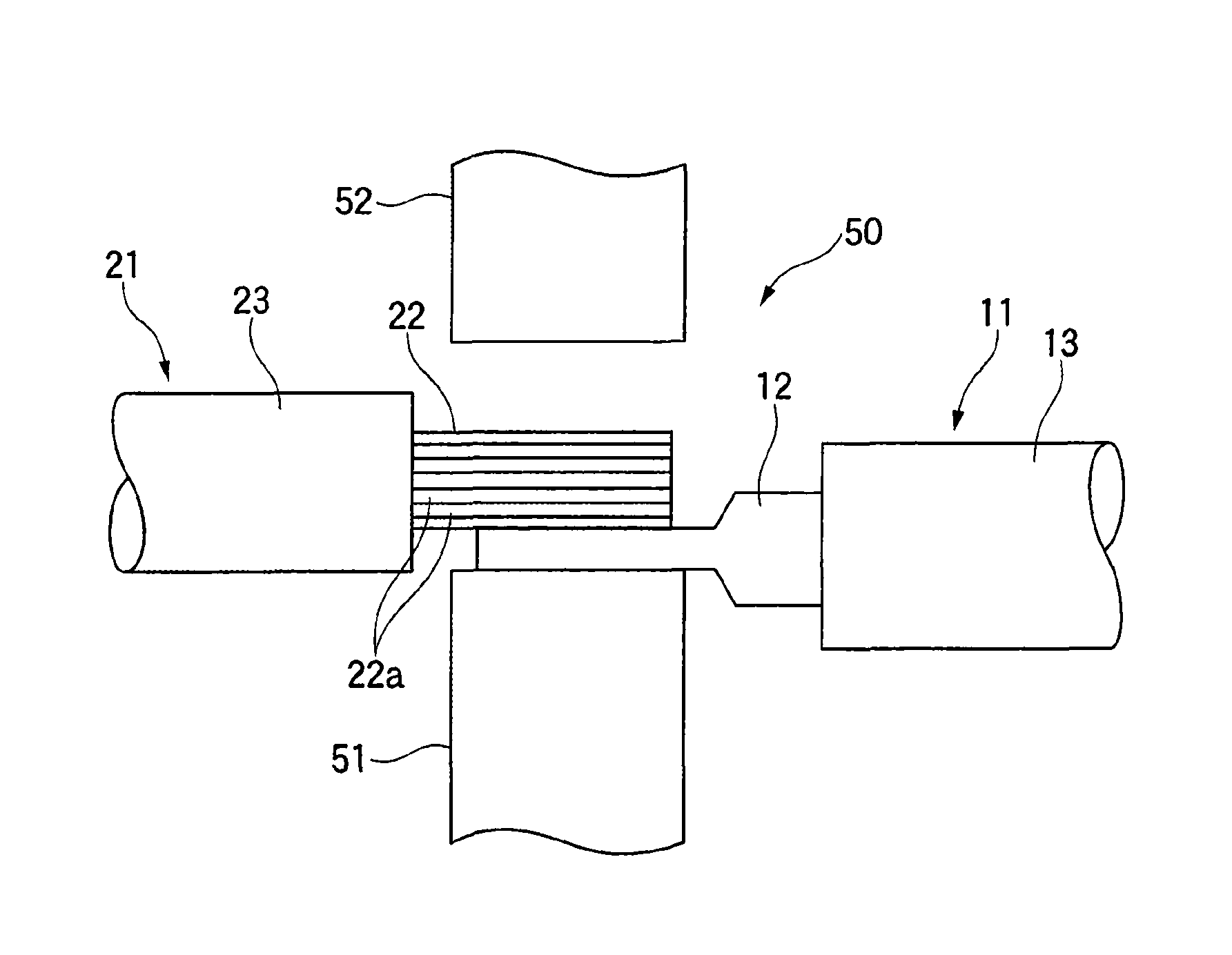
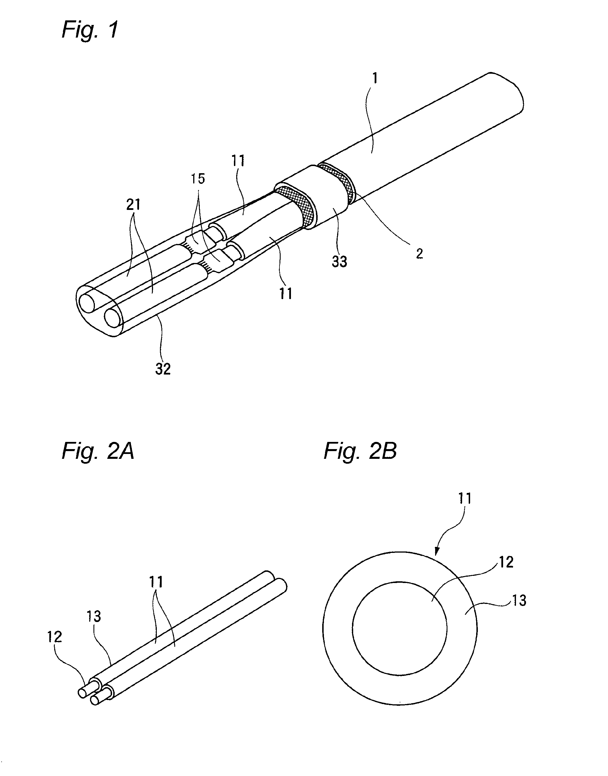
[0033]In an electric wire connecting method according to this embodiment, as shown in FIG. 1, rod wires (a wire) 11 and stranded wires 21 are connected together.

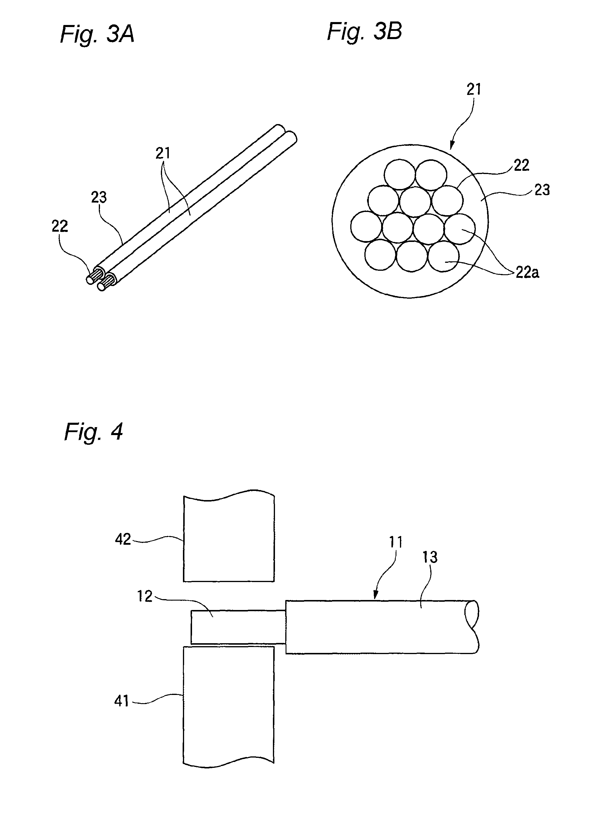
[0034]As shown in FIGS. 2A and 2B, one rod wire 11 has one conductor 12 made of aluminum and a skin 13 made of synthetic resin which is provided around the conductor 12 so as to cover it. In FIGS. 1 to 2B, two rod wires 11 are shown as being aligned side by side. The rod wires 11 are configured as conductors of a cabtyre cable 1, and the rod wires 11 are covered therearound by a braided shield 2.

[0035]As shown in FIGS. 3A and 3B, one stranded wire 21 has a conductor 22 into which plural strands 22a each made of copper or a copper alloy are twisted and a skin 23 made of synthetic resin which is provided around the conductor 22 so as to cover it. In FIG. 3, two stranded wires 21 are shown as being aligned side by side.

[0036]The con...


PUM

PropertyMeasurementUnit
diametersaaaaaaaaaa
shapeaaaaaaaaaa
transparentaaaaaaaaaa

Abstract

An electric wire connecting method for connecting together a wire having a conductor and a stranded wire having a plurality of strands which are twisted, the electric wire connecting method is provided. The electric wire connecting method includes a forming step and a welding step. In the forming step, the conductor is formed into a plate element by pressing the conductor. In the welding step, the strands are welded to the plate element in a state where the strands are superposed on the plate element.

Description

CROSS REFERENCE TO RELATED APPLICATIONS[0001]This application is a continuation of PCT application No. PCT / JP2012 / 068900, which was filed on Jul. 19, 2012 based on Japanese Patent Application (No. 2011-159123) filed on Jul. 20, 2011, the contents of which are incorporated herein by reference.BACKGROUND OF THE INVENTION[0002]1. Field of the Invention[0003]The present invention relates to an electric wire connecting method for connecting together conductors of electric wires for establishing an electric communication therebetween.[0004]2. Description of the Related Art[0005]For example, in wiring harnesses which are laid in a motor vehicle, electric wires of the wiring harnesses are connected together to distribute circuits. As a connecting method for connecting together electric wires of such wiring harnesses, there is known a connecting method for crimp connecting the electric wires by use of a sleeve (for example, refer to PTL 1).[0006][PTL 1] JP-A-5-94860SUMMARY OF THE INVENTION[0...

Claims


Application Information

Patent Timeline
Patent Type & Authority Patents(United States)
IPC IPC(8): B23K31/02H01R4/02H01R4/62H01R43/02
CPCH01R4/021H01R4/625H01R43/0207
Inventor KATAOKA, MASAYUKI
Owner YAZAKI CORP
Learn More