Golf club shaft

a golf club and shaft technology, applied in the field of golf club shafts, can solve the problems of circumferential variation and variation in flexural rigidity

Active Publication Date: 2015-01-20
SUMITOMO RUBBER IND LTD
View PDF23 Cites 2 Cited by
  • Summary
  • Abstract
  • Description
  • Claims
  • Application Information

AI Technical Summary

Benefits of technology

[0012]The appearance of the golf club having the head and the shaft attachable to and detachable from each other makes the circumferential uniformity more important.
[0013]It is an object of the present invention to provide a golf club shaft having excellent circumferential uniformity.

Problems solved by technology

In the shaft, material error and error of a winding operation or the like may cause variation.
In particular, the errors may cause circumferential variation.
In particular, the error may cause variation in a flex (flexural rigidity) in a circumferential direction.
The variation may cause various problems.
In this type of golf club, particularly, the variation of the shaft causes a problem.

Method used


Image

  • Golf club shaft
  • Golf club shaft
  • Golf club shaft

Examples


example 1

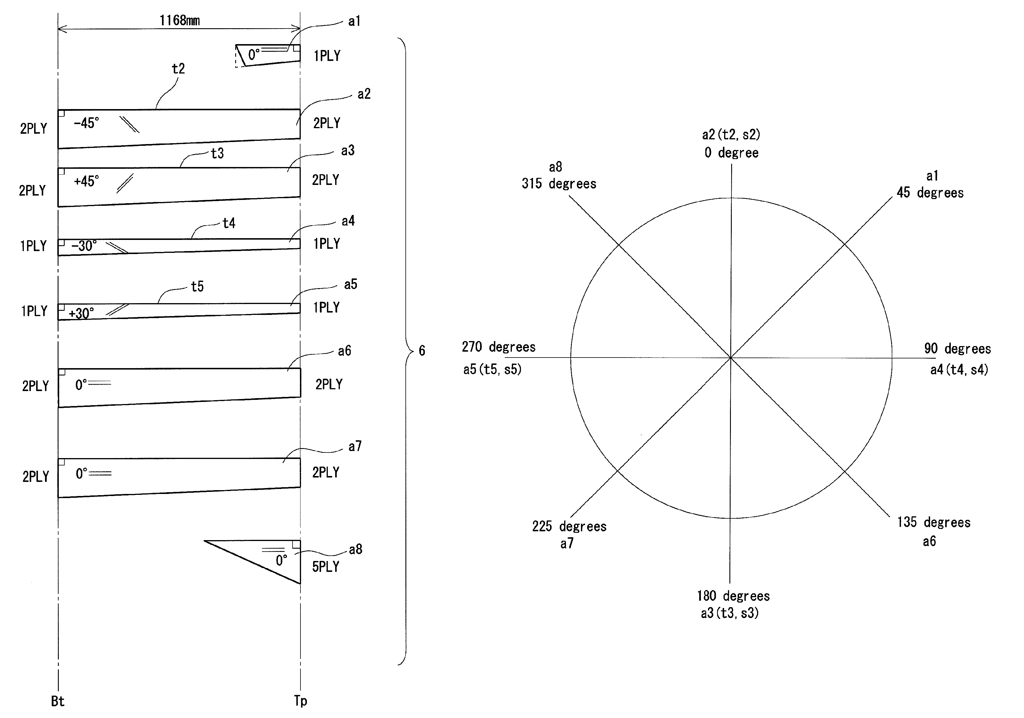
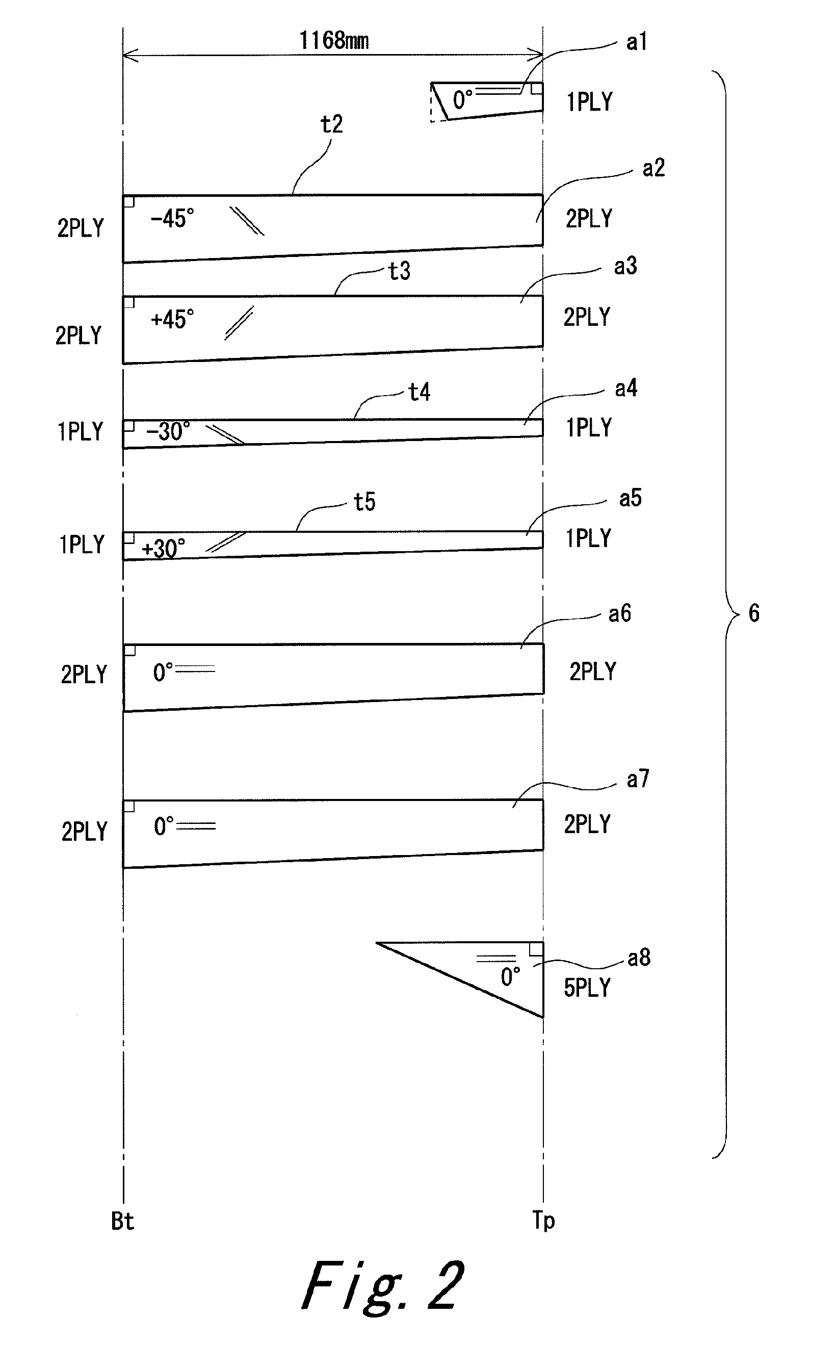
[0147]A shaft having the same laminated constitution as that of the above-mentioned first embodiment (shaft 6) was produced. Sheets shown in FIG. 2 were obtained by the cutting process. The sheets were laminated as shown in FIG. 3. That is, a base sheet a2 and a base sheet a3 were laminated so that the base sheet a2 and the base sheet a3 were deviated for 180 degrees (±15 degrees) in a circumferential direction, to obtain an united sheet a23. An adjusting sheet a4 and an adjusting sheet a5 were laminated so that the adjusting sheet a4 and the adjusting sheet a5 were deviated for 180 degrees (±15 degree) in the circumferential direction, to obtain an united sheet a45. The winding start position of the united sheet a23 and the winding start position of the united sheet a45 were made to differ by 90 degrees in the winding process. As these results, the constitution of bias layers as shown in FIG. 5 was obtained. The winding start positions of the eight sheets were dispersed in eight po...

example 2

[0148]Laminating was performed as shown in FIG. 6. That is, four bias sheets a2, a3, a4, and a5 were laminated, to obtain an united sheet. The united sheet was wound to obtain a laminated constitution shown in FIG. 7. Winding start positions were dispersed in eight positions at intervals of 45 degrees. The winding start positions of the sheets were substantially made equivalent to those of FIG. 4. A shaft of example 2 was obtained in the same manner as in example 1 except for above. The laminated constitution of the shaft of example 2 and a trade name of a prepreg used are shown in the following Table 1. The evaluation results of the shaft are shown in the following Table 3.

example 3

[0149]A shaft of example 3 was obtained in the same manner as in example 1 except that the fiber angle Af of an adjusting sheet was changed to ±25 degrees from ±30 degrees. The laminated constitution of the shaft of example 3 and a trade name of a prepreg used are shown in the following Table 1. The evaluation results of the shaft are shown in the following Table 3.


PUM


Abstract

A golf club shaft is manufactured using a plurality of prepreg sheets a1 to a8. The plurality of prepreg sheets a1 to a8 includes full length sheets a2 to a7 disposed all over in a shaft axis direction and partial sheets a1 and a8 partially disposed in the shaft axis direction. The number of plies is substantially an integer in all the full length sheets a2 to a7. The full length sheets a2 to a7 include four or more bias sheets a2 to a5. Circumferential winding start positions of the bias sheets a2 to a5 are dispersed in four or more positions. Preferably, the circumferential winding start positions of the full length sheets a2 to a7 are dispersed in five or more positions.

Description

[0001]The present application claims priority on Patent Application No. 2011-91831 filed in JAPAN on Apr. 18, 2011, the entire contents of which are hereby incorporated by reference.BACKGROUND OF THE INVENTION[0002]1. Field of the Invention[0003]The present invention relates to a golf club shaft.[0004]2. Description of the Related Art[0005]A so-called carbon shaft has been known as a golf club shaft. A sheet winding method has been known as a method for manufacturing the carbon shaft. In the sheet winding method, a laminated constitution is obtained by winding a prepreg (prepreg sheet) around a mandrel.[0006]In the shaft, material error and error of a winding operation or the like may cause variation. In particular, the errors may cause circumferential variation. In particular, the error may cause variation in a flex (flexural rigidity) in a circumferential direction. When the variation exists, the flex is changed by a circumferential relative position (hereinafter, also referred to...

Claims


Application Information

Patent Timeline
Patent Type & Authority Patents(United States)
IPC IPC(8): A63B53/10A63B102/32
CPCA63B53/10A63B2209/02
Inventor YASHIKI, TATSUYA
Owner SUMITOMO RUBBER IND LTD
Why Eureka
Try Eureka