Shelter
a technology of a shelter and a lid is applied in the field of shelters, which can solve the problems of high risk of objects of value stored in the shelter, and achieve the effects of reliable and energy-saving cooling of the enclosure interior and high protection against damag
- Summary
- Abstract
- Description
- Claims
- Application Information
AI Technical Summary
Benefits of technology
Problems solved by technology
Method used
Image
Examples
first embodiment
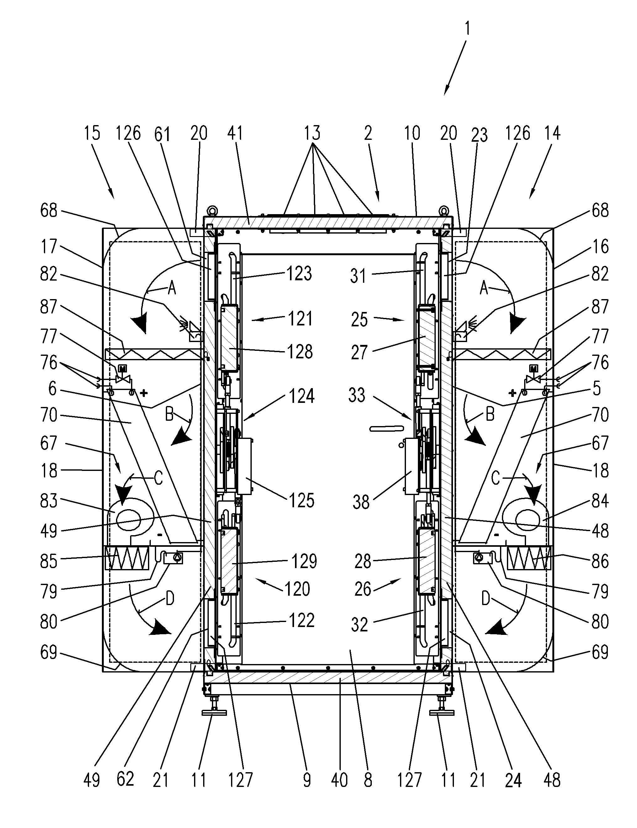
[0070]FIG. 4 shows an air-conditioning module 65 which can be used as an air-conditioning module 14, 15 for shelter 1 described above. To this end, air-conditioning module 65 has a container 66 for receiving a cooling device 67 that has the same features as the previously described containers 16, 17. In the upper part of the container space a curved return air deflector 68 is arranged and in the lower region a curved supply air deflector 69 is arranged which serve for deflecting the air flow path away from return air duct opening 23 and toward supply air duct opening 24. Deflectors 68, 69 substantially extend over the entire width of rear wall 18 and of lateral casing 19 of container 66 in order to achieve an energy-saving and optimum flow through the container space. In particular, a reduction of the outwardly acting pressure and thus a smaller power consumption of a ventilation device 83, 84 is thus achieved.
[0071]Cooling device 67 comprises a heat exchanger in the form of a cool...
second embodiment
[0078]FIG. 5 shows an air-conditioning module 90 which can be used as an air-conditioning module 14, 15 for shelter 1 described above. Air-conditioning module 90 is identical in construction to the previously described air-conditioning module 65 with the difference that the cooling device 91 therein uses a heat exchanger in the form of a cooling battery 92 whose cooling fluid is provided by a cold water aggregate 93.
[0079]Cold water aggregate 93 is located outside container 66 of air-conditioning module 90 and is connected to the coolant pipes of the cold water operated heat exchanger 92 by corresponding plug-in couplings 94 projecting from rear wall 18 of container 66. For an energy-saving operation, the cold water circuit is preferably equipped with components for energy conservation, in particular a device for cooling the fluid without operating the compression cooling unit(“free-cooling”) by utilizing the outside temperature, in particular below 12° Celsius.
[0080]Heat exchanger...
third embodiment
[0081]FIG. 6 shows an air-conditioning module 100 which can be used as an air-conditioning module 14, 15 for the shelter 1 described above. Air-conditioning module 100 differs from the previously described air-conditioning modules 65, 90 both by its container 101 and by the cooling device 102 accommodated therein. Individual components of substantially identical construction are designated by the same reference numerals.
[0082]Cooling device 102 comprises a finned heat exchanger 103 that extends substantially over the entire height of container 101. In order to further optimize the surface 104 available for the heat exchange, heat exchanger 103 is inclined in the container space, its lower border 116 being located at a greater distance from rear wall 18 than its upper border 117. The lateral borders 105 of heat exchanger 103 substantially extend over the entire width of lateral casing 19 of container 101.
[0083]Heat exchanger 103 is used as a dissipator for liquid cooling. The latter...
PUM
 Abstract
Description
Claims
Application Information
 - R&D
- Intellectual Property
- Life Sciences
- Materials
- Tech Scout
- Unparalleled Data Quality
- Higher Quality Content
- 60% Fewer Hallucinations
Browse by: Latest US Patents, China's latest patents, Technical Efficacy Thesaurus, Application Domain, Technology Topic, Popular Technical Reports.
© 2025 PatSnap. All rights reserved.Legal|Privacy policy|Modern Slavery Act Transparency Statement|Sitemap|About US| Contact US: help@patsnap.com


