
Cooling system and freight container

a cooling system and freight container technology, applied in the field of cooling systems and freight containers, can solve the problems of increasing the weight of aircraft air conditioners equipped with two independent climate control systems, increasing the consumption of energy, and inability to interrupt the cold chain in many cases, so as to achieve simple and more cost-effective linkage, simple and convenient maintenance of cooling stations, and the effect of reducing the number of freight containers

Active Publication Date: 2012-07-24
AIRBUS OPERATIONS GMBH
View PDF22 Cites 5 Cited by
  • Summary
  • Abstract
  • Description
  • Claims
  • Application Information

AI Technical Summary

Benefits of technology

The patent describes a system for cooling items of freight on board an aircraft using a refrigerating device and a cooling station. The refrigerating device is connected to the cooling station through a cooling circuit, which circulates the refrigerant medium with the aid of a conveying device. The cooling station can be connected to the freight compartment or to a separate insulated zone of the aircraft. The system is integrated into the central cooling system of the aircraft, and individual cooling stations can be positioned at various locations within the aircraft. The system provides reliable and energy-efficient cooling for the freight, reduces the load on the air-conditioning unit, and allows for precise temperature control. The system can be easily controlled and monitored, and it is designed to circulate the cold air back into the cooling station for further cooling.

Problems solved by technology

However, many items of freight also have to be cooled during transportation, in which connection an interruption of the cold-chain is in many cases not desired or permitted.
An aircraft air-conditioning unit equipped with two independent climate-control systems is relatively complex and expensive.
Furthermore, an aircraft air-conditioning unit of such a type has an increased weight and also an increased consumption of energy.
Lastly, in the event of a heightened cooling requirement of the cabin, adequate air conditioning of the freight compartment can no longer be ensured in some circumstances, since the second climate-control system which is actually provided for the purpose of air-conditioning the freight compartment is automatically called upon for the purpose of assisting the first climate-control system for air-conditioning the aircraft cabin.
A further disadvantage of the cooling of the freight compartment or freight-compartment zone with the aid of the air-conditioning unit of the aircraft consists in the fact that the air-conditioning unit of the aircraft has only a limited cooling capacity.
Lastly, in the case of the cooling of the freight compartment or freight-compartment zone with the aid of the air-conditioning unit of the aircraft the entire freight compartment, or at least a relatively large freight-compartment zone, is cooled, so that items of freight that have to be transported at relatively high temperatures cannot be loaded into the same freight compartment or freight-compartment zone.
As a consequence, in some circumstances the freight-transport capacity of the aircraft cannot be utilised optimally.
However, the lowest temperature of −20° C. is attained in this case only in the unstable state—i.e. a constant cooling at −20° C. is not possible.
However, special containers of such a type, which are cooled with the aid of dry ice, exhibit the disadvantage that an elaborate consumption calculation—which is dependent on various factors such as, for example, the environmental conditions, the useful load and also the target temperature—for determining the quantity of dry ice to be additionally loaded into the storage tank is required prior to loading.
Furthermore, by virtue of the requirement of having to add to the load up to 300 kg of dry ice, and also by reason of the weight of the further components that are required for the cooling of the container, the special container exhibits a higher empty weight and consequently a diminished loading capacity.
Moreover, the service life is limited by reason of the limited storage capacity in respect of dry ice and also by reason of the limited battery capacity of the fan.
Further disadvantages arise directly through the use of dry ice by way of heat-sink.
For example, by reason of the fact that no fully uniform distribution of the air over the items of freight is possible with the fan that is employed for distributing the cooled air, the cooling with dry ice results in an inhomogeneous temperature distribution in the container.
Furthermore, dry ice releases CO2 and therefore has to be declared as a hazardous material.

Method used


Image

  • Cooling system and freight container
  • Cooling system and freight container
  • Cooling system and freight container

Examples


first embodiment

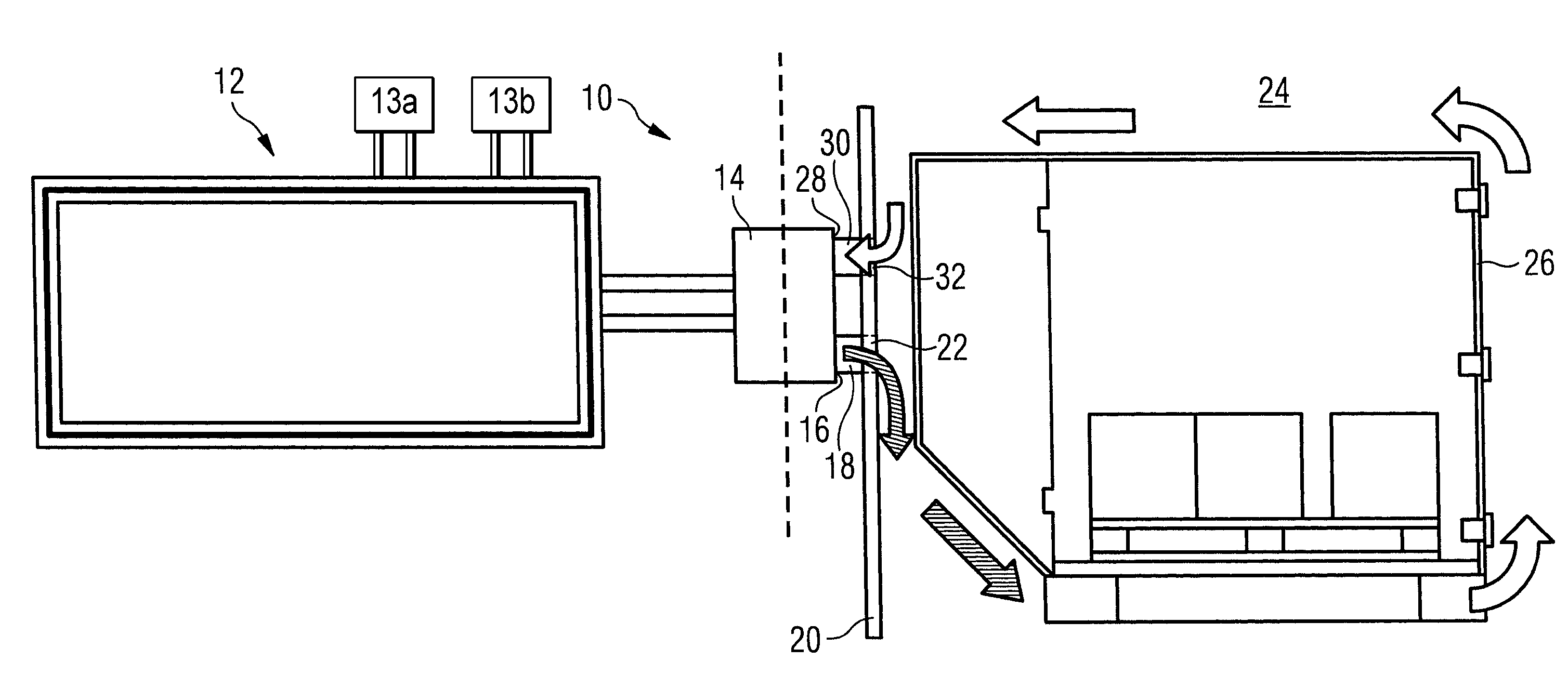
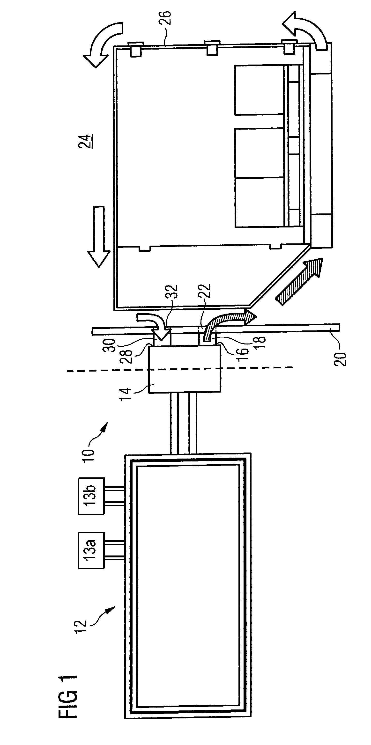
[0054]a system 10 for cooling items of freight on board an aircraft is shown in FIG. 1. The system 10 is integrated into a central cooling system 12 of the aircraft, which includes a refrigerating device and also a plurality of cooling stations. The cooling stations of the central cooling system are connected to the refrigerating device via a cooling circuit in which Galden.RTM. HAT 135, obtainable from Solvay Solexis, by way of refrigerant medium is circulated by a pump. Via the refrigerant medium the cooling energy generated by the refrigerating device is supplied to the individual cooling stations. In the cooling circuit, electronically selectable valves are arranged upstream of each cooling station, which in the closed state prevent the supply of refrigerant medium, and consequently cooling energy, to the respective cooling station, and in the open state permit the supply of refrigerant medium, and consequently cooling energy, to the respective cooling station.

[0055]Some cooling...

second embodiment

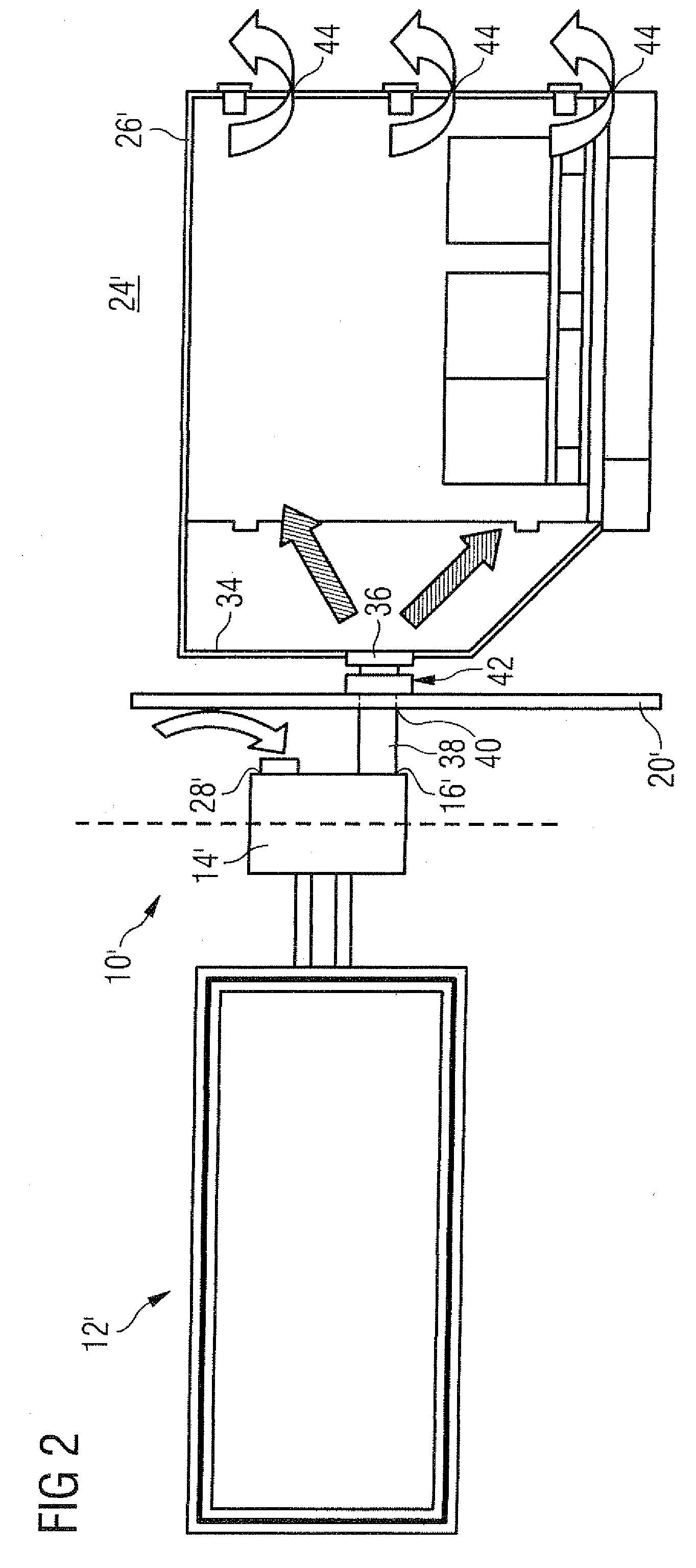
[0059]FIG. 2 shows a system 10′ for cooling items of freight on board an aircraft. The system 10′ for cooling items of freight on board an aircraft is, like the system 10 represented in FIG. 1, integrated into a central cooling system 12′ of the aircraft with a refrigerating device and also with a plurality of cooling stations to which cooling energy generated by the refrigerating device is supplied by a refrigerant medium which is circulated in a cooling circuit by a pump. A cooling station 14′ of the system 101 for cooling items of freight on board an aircraft is, as in the case of the system 10 shown in FIG. 1, installed in a freight-compartment region in the lateral triangular regions of the aircraft.

[0060]As distinct from the system 10 represented in FIG. 1, however, in the case of the system 10′ shown in FIG. 2 for cooling items of freight on board an aircraft an air outlet 16′ of the cooling station 14′ is directly connected to an air inlet 36 provided in a freight-container ...

third embodiment

[0065]a system 10″ for cooling items of freight on board an aircraft is shown in FIG. 4. The system 10″ for cooling items of freight on board an aircraft is once again integrated into a central cooling system 12″ of the aircraft. The central cooling system 12″ of the aircraft includes a refrigerating device which is connected to a plurality of cooling stations via a cooling circuit, in order to supply cooling energy generated by the refrigerating device to the cooling stations by means of a refrigerant medium which is circulated in the cooling circuit by a pump.

[0066]As distinct from the systems 10, 10′ discussed above, however, the cooling station 14″ of the system 10″ shown in FIG. 4 for cooling items of freight on board an aircraft is not permanently installed in the region of a freight compartment 24″ of the aircraft but is integrated into a freight container 26″ for receiving items of air freight to be subjected to cold storage.

[0067]For the purpose of linking the cooling stati...


PUM


Abstract

A system for cooling items of freight on board an aircraft includes a refrigerating device and also a cooling station to which cooling energy generated by the refrigerating device is supplied by a refrigerant medium. The cooling station is capable of being connected to a freight compartment of the aircraft or to a freight container on board the aircraft, in order to lead the cooling energy supplied to the cooling station away into the freight compartment or into the freight container. A freight container for receiving items of freight designated for transportation on board an aircraft is capable of being connected to a cooling station of a system for cooling items of freight on board an aircraft, so that the cooling energy supplied to the cooling station is capable of being led away into the freight container.

Description

[0001]This application claims the benefit of International Application No.[0002]PCT / EP2007 / 003218, filed on Apr. 11, 2007, and German Application No. DE 10 2006 017 012.1, filed on. Apr. 11, 2006.TECHNICAL FIELD[0003]The invention relates to a system for cooling items of freight on board an aircraft and also to a freight container, capable of being connected to the cooling system, for receiving items of freight designated for transportation on board an aircraft.BACKGROUND[0004]The transportation of items of freight by air is increasingly gaining in importance, in particular by reason of the very short transportation-times that are possible in this case. However, many items of freight also have to be cooled during transportation, in which connection an interruption of the cold-chain is in many cases not desired or permitted. In order to guarantee appropriate storage conditions for items of freight to be subjected to cold storage during transportation on board an aircraft, two differe...

Claims


Application Information

Patent Timeline
Patent Type & Authority Patents(United States)
IPC IPC(8): B60H1/32
CPCB64D13/00Y02T50/44Y02T50/56Y02T50/50Y02T50/40
Inventor ULUC, OZANKIRYAMAN, KAYIHAN AHMETWITSCHKE, MATTHIAS
Owner AIRBUS OPERATIONS GMBH
Learn More