
System and method for routing around failed links

a system and link technology, applied in the field of system and link routing, can solve problems such as packet loss, link may fail, and hundreds of lost packets

Active Publication Date: 2015-01-27
GOOGLE LLC
View PDF4 Cites 73 Cited by
  • Summary
  • Abstract
  • Description
  • Claims
  • Application Information

AI Technical Summary

Benefits of technology

The patent text describes a way to prevent network traffic from being lost during a period of network convergence. This is done by rerouting packets through an alternate route instead of dropping them. This helps to ensure that the traffic makes it to its destination without any issues.

Problems solved by technology

In any multi-stage network, a link may fail.
Because such networks may operate at speeds of 10-100 Gbps, such packet loss during this period can amount to hundreds of lost packets.

Method used


Image

  • System and method for routing around failed links
  • System and method for routing around failed links
  • System and method for routing around failed links

Examples


Embodiment Construction

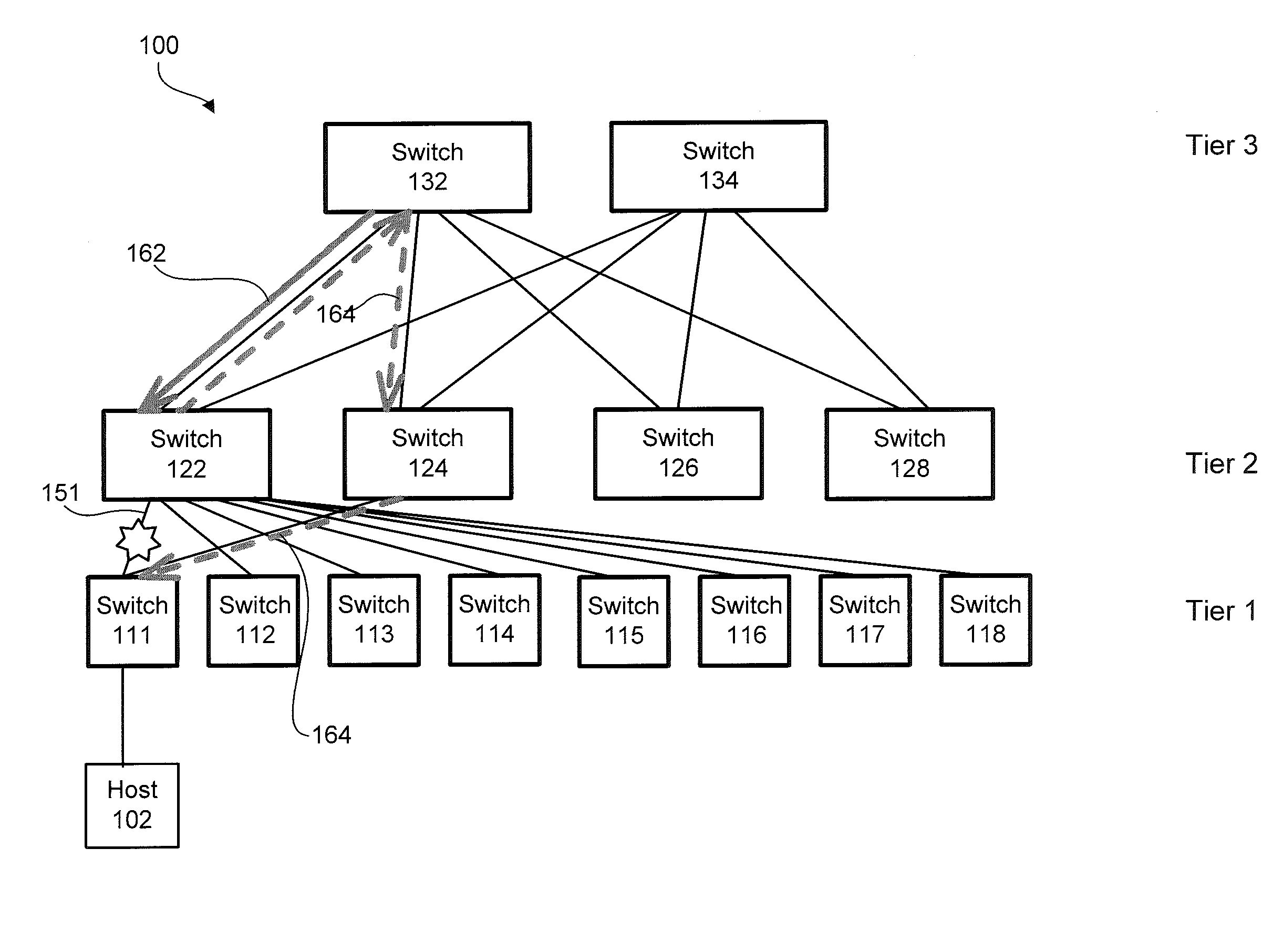
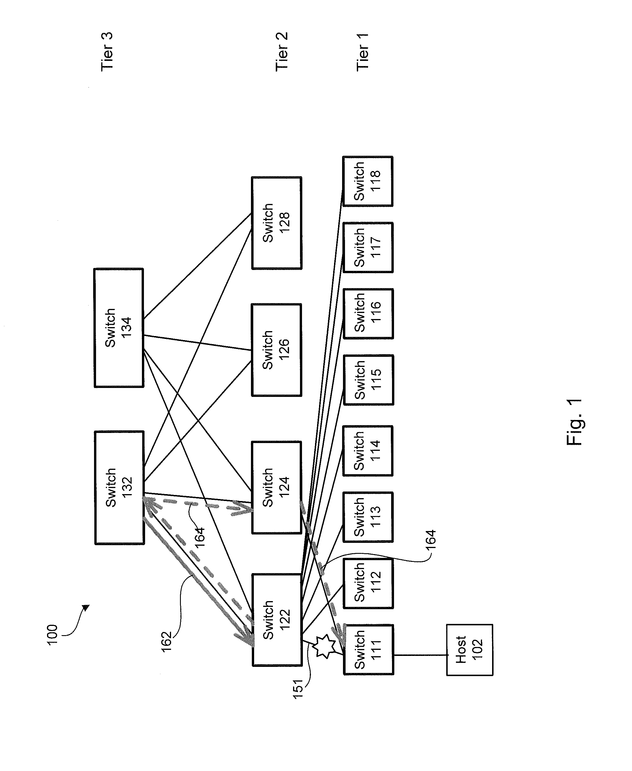
[0010]FIG. 1 illustrates a multi-stage network 100, including a first stage (Tier 1) having a first plurality of switches 111-118, a second stage (Tier 2) having a second plurality of switches 122, 124, 126, 128, and a third stage (Tier 3) having switches 132, 134. While a three stage network is shown, it should be understood that any number of stages may be used. Each of the Tier 1 switches 111-118 may be coupled to host devices, such as host device 102. The host devices may be, for example, network servers or other computing devices. Each Tier 1 switch 111-118 may further be coupled to one or more of the Tier 2 switches 122-128. For example, each Tier 1 switch 111-118 may be coupled to each Tier 2 switch 122-128. Similarly, each Tier 2 switch 122-128 may be coupled to all or fewer Tier 3 switches 132-134.

[0011]In this example, a link 151 between the switch 122 and the switch 111 is down. Thus, while a path 162 may be predetermined as a priority path from the switch 132 to the swit...


PUM


Abstract

A multi-stage network may include a first stage having a first plurality of switches, a second stage having a second plurality of switches, and a number of links between the first and second stages. A controller in communication with the first plurality of switches and the second plurality of switches may determine a priority path to be utilized by each switch in sending information and a fallback path. If the priority path includes a failed link, the controller implements in one or more of the switches the fallback path for sending the information. The fallback path may, for example, cause the information to be transmitted through a peer router.

Description

BACKGROUND OF THE INVENTION[0001]In some networks, such as software defined networks or OpenFlow™ networks, control plane tasks are cleanly separated from data plane tasks. For example, forwarding entities, such as routers or switches, only perform the data plane tasks, such as forwarding packets between various ports after applying modification to the packet's encapsulation such as modifying a header. A separate control server may perform the control plane tasks, such as learning about media access control (MAC) address, participating in routing algorithms, learning about various routes, performing various neighbor discovery related tasks and gleaning about address mapping etc. The forwarding entities talk to the controller using a protocol specified by OpenFlow™ specification. When control plane tasks, such as routing, running on the OpenFlow™ controller determine a route about various prefixes, the controller will translate the route to a flow and push these flows to the forwardi...

Claims


Application Information

Patent Timeline
Patent Type & Authority Patents(United States)
IPC IPC(8): H04L12/26H04L45/28
CPCH04L45/28H04L45/02H04L45/22H04L41/0668H04L41/40
Inventor PANI, AYASKANTSINGH, ARJUN
Owner GOOGLE LLC
Learn More