
Upright vacuum cleaner

a vacuum cleaner and upright technology, applied in the direction of suction cleaners, cleaning equipment, suction hoses, etc., can solve the problems of reducing the efficiency of cleaning, the main cleaner head is usually too heavy and cumbersome, and the main cleaner is usually completely impractical for this purpose. , to achieve the effect of reducing the weigh

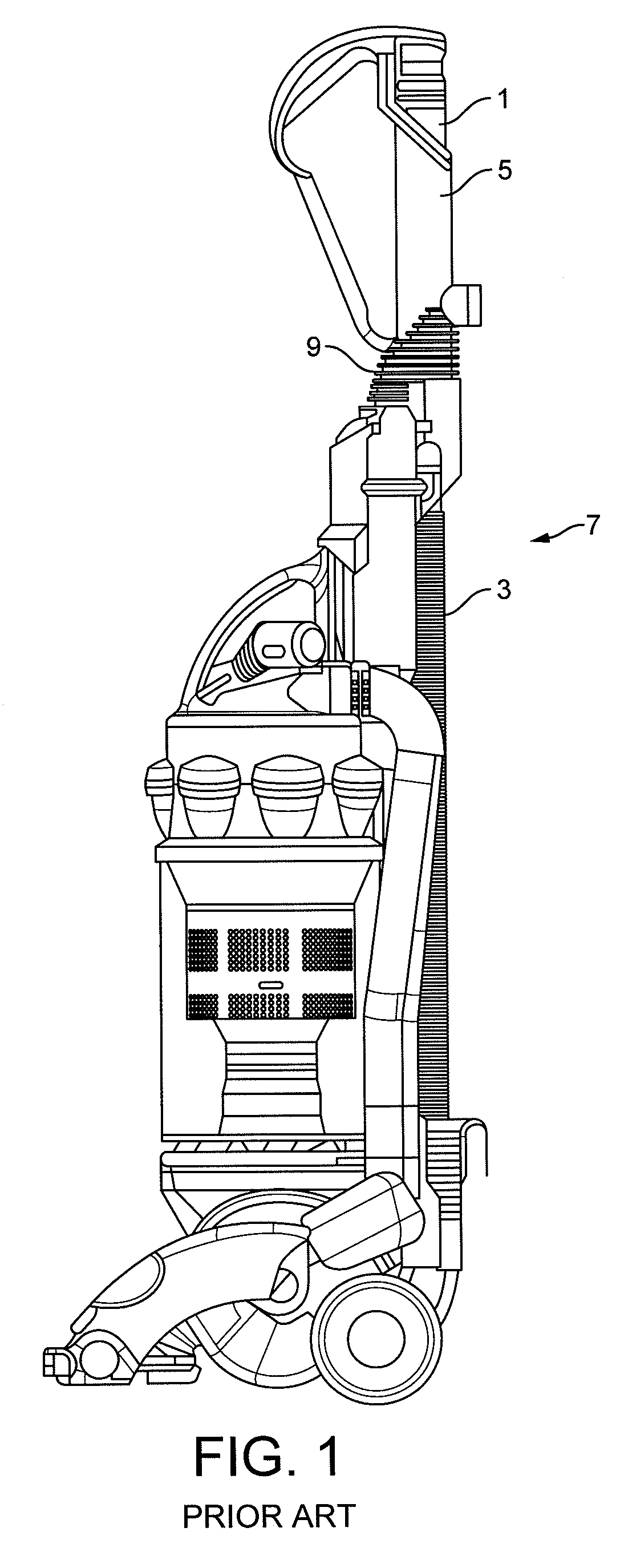
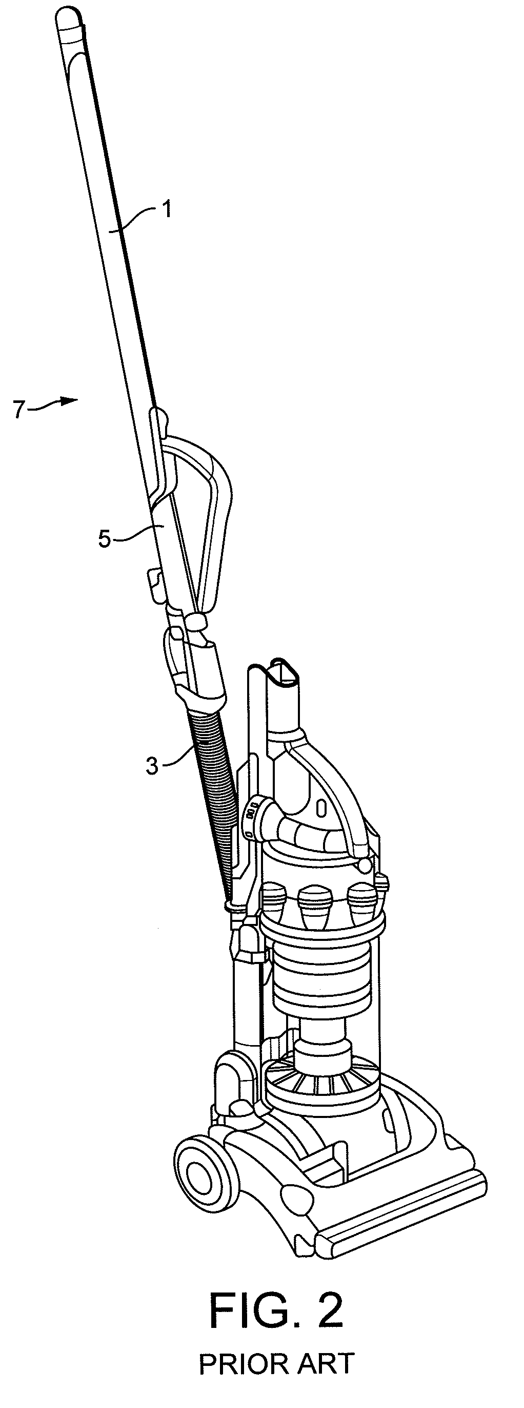
Inactive Publication Date: 2015-02-03
DYSON TECH LTD
View PDF23 Cites 1 Cited by
  • Summary
  • Abstract
  • Description
  • Claims
  • Application Information

AI Technical Summary

Benefits of technology

[0007]According to the present invention, there is provided an upright vacuum cleaner comprising a wand fluidly connected to a separating apparatus on the cleaner via a hose and which is used, as required, to clean above the level of the floor, the wand being at least partly retractable inside the hose for storage, a hose catch being provided at the end of the hose, the hose catch being biased towards a locking position in which the hose catch locks the wand in an extended position, the hose being a stretch hose arranged, in its coil-bound state, to act as a reaction member against which a user may readily force the biased hose catch out of said locking position using the extended wand.
[0023]In one embodiment, the wand comprises a second locking feature for co-operating with the locking member, this second locking feature being positioned on the upper wand section above the first locking feature such that when the handle is in the raised position, the locking member in its release position sits axially between the first and second locking features, the relative axial position of the locking member and the second locking feature being such that sliding the upper wand upwards engages the locking member with the second locking feature before the lower wand section can slide out of keying engagement with the inlet duct assembly. Thus, if the user accidentally knocks upwards against the lower wand section—which lower wand section may extend above the upper end of the hose even when it is retracted inside the hose—upward movement of the lower wand section is advantageously arrested before the lower wand section can slide out of keying engagement with the inlet duct assembly—ensuring that the function of the wand as a torsion brace is maintained.

Problems solved by technology

It is usually completely impractical to use the main cleaner head for this purpose: the cleaner will almost certainly be too heavy and cumbersome, and the cleaner head itself too large.

Method used


Image

  • Upright vacuum cleaner
  • Upright vacuum cleaner
  • Upright vacuum cleaner

Examples


Embodiment Construction

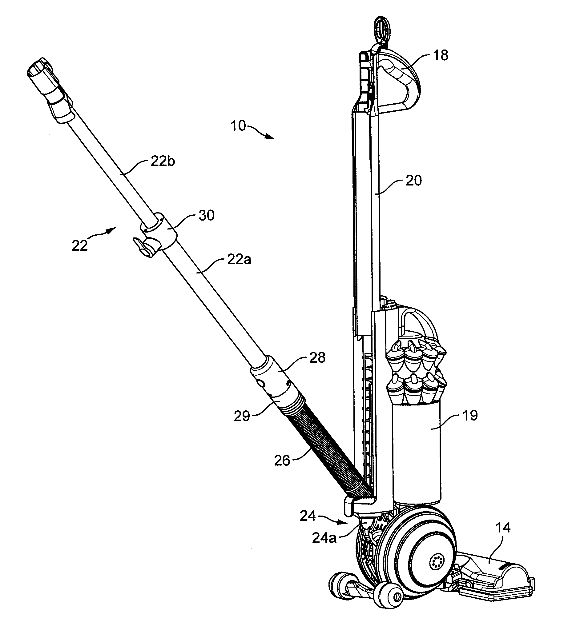
[0048]FIG. 3 shows an upright vacuum cleaner 10.

[0049]The cleaner 10 has a rolling head assembly 12 which carries a fixed cleaner head 14, and an ‘upright’ body 16 which can be reclined relative to the head assembly 12 and which includes a handle 18 for maneuvering the cleaner 10 across the floor. In use, a user grasps the handle 18 and reclines the upright body 16 until the handle 18 is disposed at a convenient height for the user; the user can then roll the vacuum cleaner 10 across the floor using the handle 18 in order to pick up dust and other debris on the floor. The dust and debris is drawn in through a downward-facing suction inlet on the cleaner head 14 by a motor-driven fan housed on-board the cleaner 10. From here, the dirt-laden air stream is ducted in conventional manner under the fan-generated suction pressure to a cyclonic separating apparatus 19, where dirt is separated from the air before the relatively clean air is then expelled back to the atmosphere.

[0050]The hand...


PUM


Abstract

An upright vacuum cleaner comprising a wand fluidly connected to a separating apparatus on the cleaner via a hose and which is used, as required, to clean above the level of the floor. The wand is at least partly retractable inside the hose for storage, and a hose catch is provided at the end of the hose, this hose catch being biased towards a locking position in which the hose catch locks the wand in an extended position. According to the invention, the hose is a stretch hose arranged, in its coil-bound state, to act as a reaction member against which a user may readily force the biased hose catch out of said locking position using the extended wand.

Description

REFERENCE TO RELATED APPLICATIONS[0001]This application claims the priority of United Kingdom Application No. 1116808.5, filed 29 Sep., 2011, the entire contents of which are incorporated herein by reference.FIELD OF THE INVENTION[0002]The present invention relates generally to upright vacuum cleaners, which includes dry, wet or “wet-and-dry” upright vacuum cleaners.BACKGROUND OF THE INVENTION[0003]Upright cleaners typically have a rolling head assembly, which carries a fixed cleaner head in plane-parallel contact with the floor surface. This head assembly is mounted on a reclining ‘upright’ body which carries a handle at its upper end. In the conventional floor-cleaning mode, a user reclines the ‘upright’ body until the handle is at a convenient height, and then uses the handle manually to push the cleaner across the floor, maintaining the cleaner head in plane parallel contact with the floor surface.[0004]It is often desirable to vacuum-clean above the level of a floor. For exampl...

Claims


Application Information

Patent Timeline
Patent Type & Authority Patents(United States)
IPC IPC(8): A47L5/28A47L9/24A47L5/32
CPCA47L9/248A47L5/32A47L9/244A47L9/242
Inventor WILLS, ANDREW JAMESMCLUCKIE, PAUL ANDREWPARK, CHARLES EDWARDDYSON, JAMESGAMMACK, PETER DAVID
Owner DYSON TECH LTD
Learn More