Hydraulic brake handle assembly

a technology of hydraulic brakes and handle assemblies, which is applied in the direction of bicycle brakes, vehicle components, cycle equipments, etc., can solve the problems of inconvenient cleaning of sand, noise and wear, and achieve the effect of improving the response time of hydraulic brake calipers

Inactive Publication Date: 2015-02-03
TIEN HSIN INDS
View PDF8 Cites 8 Cited by
  • Summary
  • Abstract
  • Description
  • Claims
  • Application Information

AI Technical Summary

Benefits of technology

[0007]The primary object of the present invention is to provide a hydraulic brake handle assembly, wherein the response time of the hydraulic brake caliper can be much improved and the brake action can be carried out immediately when the brake lever is pressed.
[0008]Another object of the present invention is to provide a hydraulic brake handle assembly which allows the brake pads of the hydraulic caliper to be assembled at a relatively large distance from the brake disc, so that sand won't get struck between the brake pads and the brake disc. So out of true brake disks can be used. This improvement reduces noise and wear of the brake pads and disc, making it easy to clean the sand and decreasing service time spent truing brake disks.

Problems solved by technology

However, this assembling method is likely to cause sand to get stuck between the brakes pads and the disc, causing noise and wear of the brake pads and disc and further causing inconvenience of cleaning the sand.
Due to the small pad clearance, even a slightly out of true brake disk can also cause undesired noise and wear.

Method used


Image

  • Hydraulic brake handle assembly
  • Hydraulic brake handle assembly
  • Hydraulic brake handle assembly

Examples


Embodiment Construction

[0023]The present invention will be clearer from the following description when viewed together with the accompanying drawings, which show, for purpose of illustrations only, the preferred embodiment in accordance with the present invention.

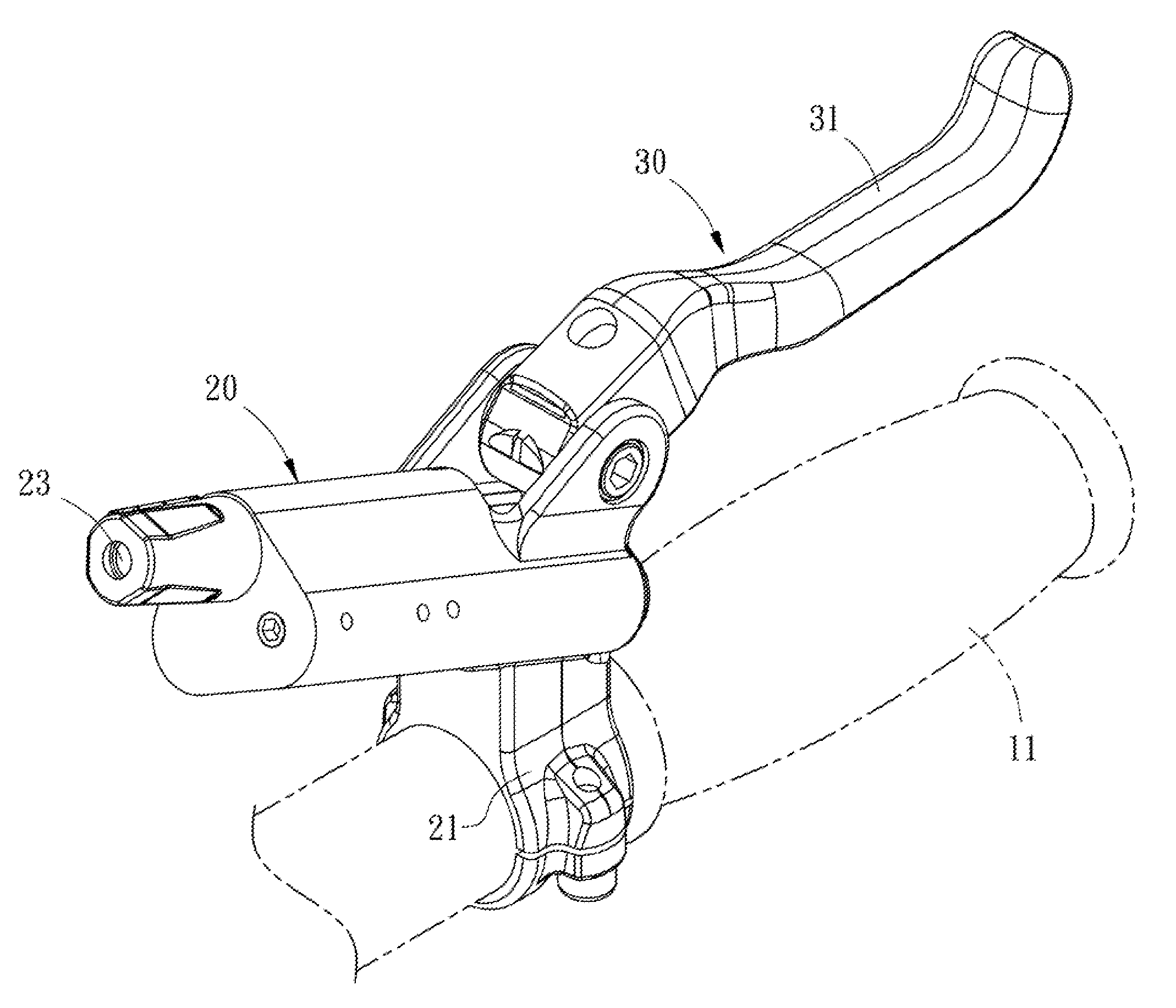
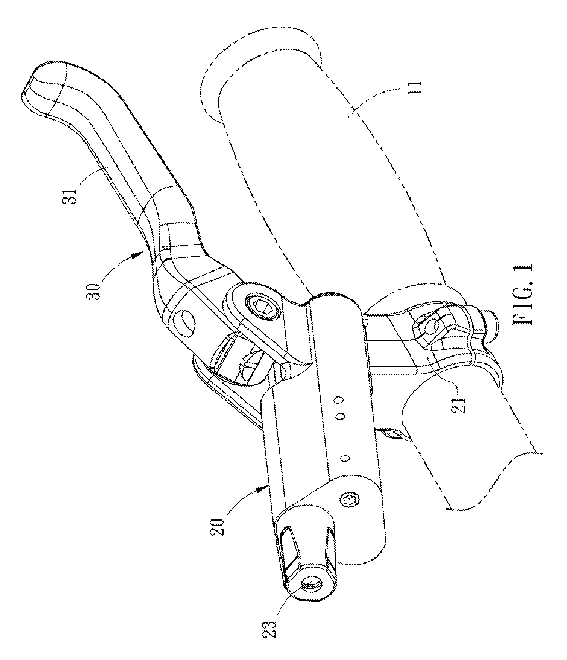
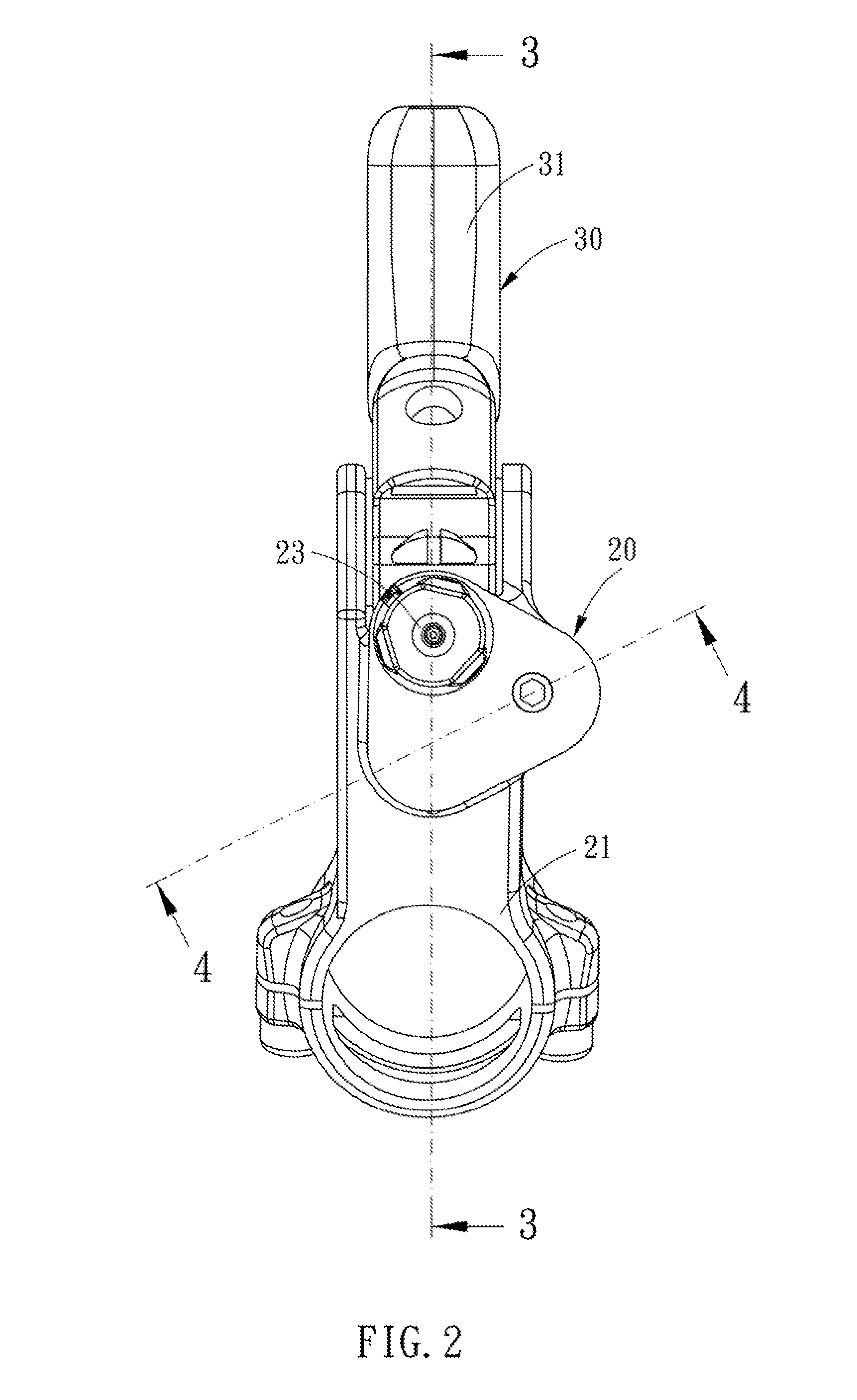
[0024]Referring to FIGS. 1-10, a hydraulic brake handle assembly in accordance with the present invention is mounted on a handlebar 11 of a bicycle to control a hydraulic brake caliper 12 and essentially comprises a body 20, a brake lever 30, a piston 40, a first spring 50 and a second spring 60.

[0025]The body 20 includes a mounting portion 21 mounted on the handlebar 11, a first oil chamber 22, an outlet 23 in communication with the first oil chamber 22, a second oil chamber 24, a first passage 251 in communication with the first and second oil chambers 22, 24, a distribution chamber 46, a front distribution passage 252 in communication with the second oil chamber 24 and the distribution chamber 26, a rear distribution passage 253 in communicati...


PUM


Abstract

A hydraulic brake handle assembly, wherein the response time of the hydraulic brake caliper can be much improved, and the brake action can be carried out immediately. When the brake lever is pressed, the volume of the oil pushed by the piston is doubled due to the hydraulic brake handle assembly is provided with two piston portions inserted in two oil chambers. Since the response time of the hydraulic caliper of the present invention is improved, it allows the brake pads of the hydraulic caliper to be assembled at a relatively large distance from the brake disc, so that sand won't get struck between the brake pads and the brake disc, and the brake disc remains useful when they are bent out of plain rubbing after using.

Description

BACKGROUND OF THE INVENTION[0001]1. Field of the Invention[0002]The present invention relates to a brake handle assembly for a bicycle, and more particularly to a hydraulic brake handle assembly for a bicycle.[0003]2. Description of Related Art[0004]Bicycle brake generally includes steel cord type brake and hydraulic type brake. The hydraulic brake is normally driven by a hydraulic brake handle assembly disposed on the handlebar of a bicycle, and in the brake handle assembly is provided a piston cylinder which is only formed with a single of chamber. Hence, the response time of the hydraulic brake caliper to the action of pressing the brake lever is relatively longer, namely, the brake action of the caliper is not immediately actuated and little delayed, when the brake lever is pressed.[0005]For the above reason, when the brake assembly is assembled, the distance between the brake pads and the brake disc of the conventional hydraulic brake is normally reduced a small extent in order...

Claims


Application Information

Patent Timeline
Patent Type & Authority Patents(United States)
IPC IPC(8): B60T11/00
CPCB62L3/023
Inventor MILES, JASON
Owner TIEN HSIN INDS
Why Eureka
Try Eureka