Dispensing device for cartridges

a cartridge and dispensing device technology, applied in the field of sealant guns, can solve the problems of inability to use the cartridge system of mixing multiple components of the gun, the manufacture of the valves proposed so far is very elaborate, and achieves the effect of easy and straightforward handling and inexpensive manufacturing

Inactive Publication Date: 2015-02-03
HERAEUS MEDICAL
View PDF165 Cites 8 Cited by
  • Summary
  • Abstract
  • Description
  • Claims
  • Application Information

AI Technical Summary

Benefits of technology

[0012]The invention is based on the object to provide a simple dispensing device for flowable materials that is easy and straightforward to handle and inexpensive to manufacture. In the scope of the present invention, flowable materials are understood to mean liquid, viscous, even highly viscous, tenacious materials that are made to flow only through the application of pressure. The flowable materials are to be dispensed through compressed gas, which, for example, is taken from an insertable gas cartridge or compressed gas cartridge that is situated in the device. Said device is to consist of as few parts as possible that can be made through inexpensive injection moulding using conventional plastic materials. For this purpose, it is necessary to develop a straightforward, simple valve system that allows the gas flow to be controlled for an application time of the dispensing device of maximally 5 minutes. The dispensing device should be mountable through few manual steps and should be manufactured without difficulty in large numbers. It is also desirable for the dispensing device to be suitable as a disposable article for single use. It would also be advantageous if the user were able to detect the operating status of the dispensing device on the outside.
[0015]Moreover, it can be advantageous that a second passage is arranged in or on the valve body, which connects the cartridge connector to a first drain in a third position of the valve body such that any over-pressure on the cartridge connector can escape through the first drain in the third position of the valve body.
[0019]Moreover, it can be advantageous that a sterile filter is arranged on at least one of the drains and / or a pressure relief valve is arranged in at least one of the drains.
[0021]Moreover, it can be advantageous that a position indicator is arranged on the rotatable valve body, in particular on the top side, on which the position of the valve body in the base body can be detected.
[0032]Moreover, the dispensing device should be designed such that at least two cartridges differing in diameters can be connected. This would allow pasty materials from different cartridge systems to be squeezed out through just one dispensing device. This feature would entail economic advantages with regard to the amortisation of the dispensing device.
[0035]Moreover, it can be advantageous to arrange, on the inside of the cartridge connectors, fixation devices for fixing cartridges in place.

Problems solved by technology

However, said gun cannot be used for cartridge systems for mixing multiple components with a static mixer.
Moreover, the manufacture of said gun is very elaborate.
Especially the valves proposed thus far are very expensive and thus make the use of the dispensing devices as disposable articles questionable.
Moreover, the proposed technical solutions are difficult to implement in the form of plastic injection moulding parts.

Method used


Image

  • Dispensing device for cartridges
  • Dispensing device for cartridges
  • Dispensing device for cartridges

Examples


Embodiment Construction

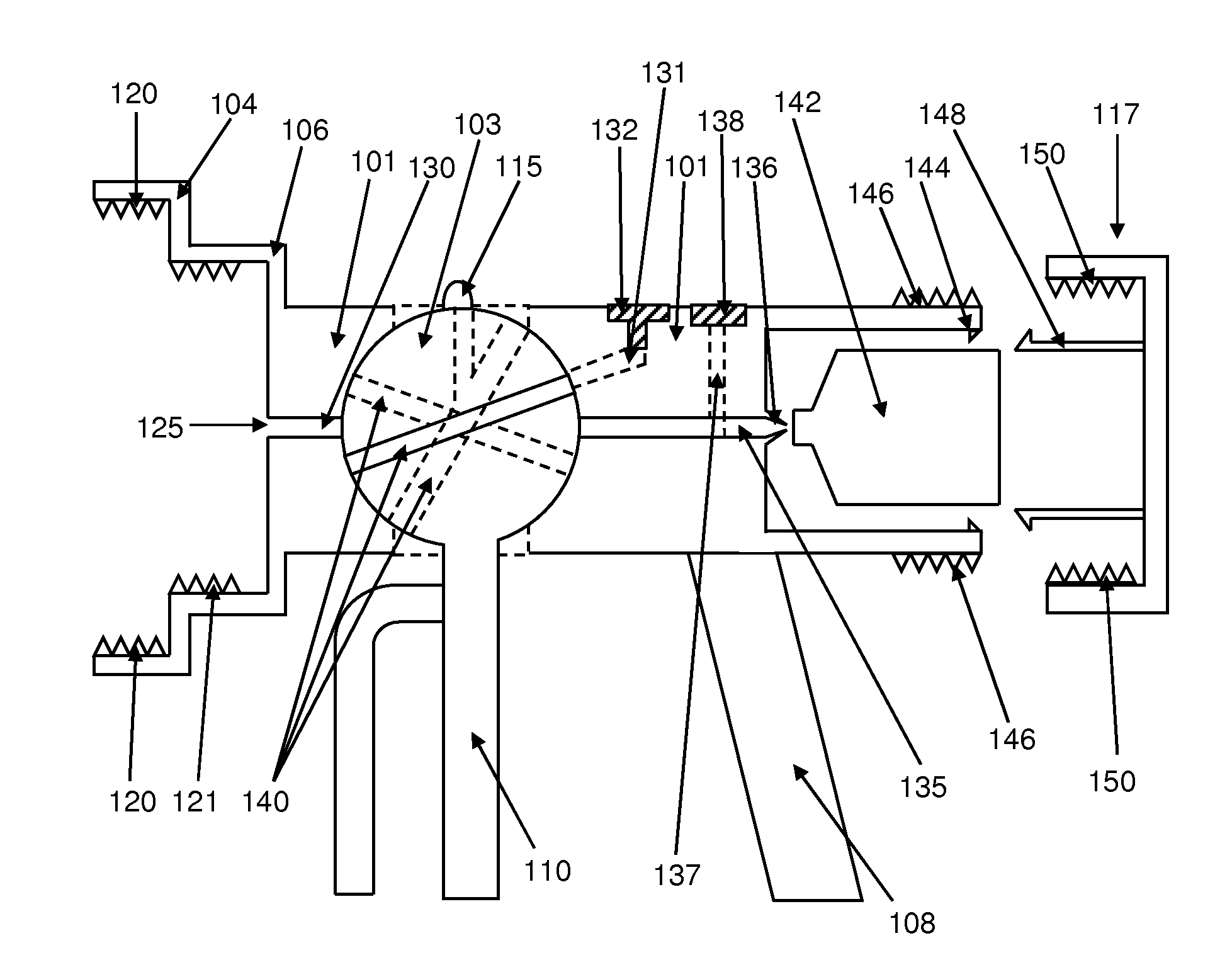
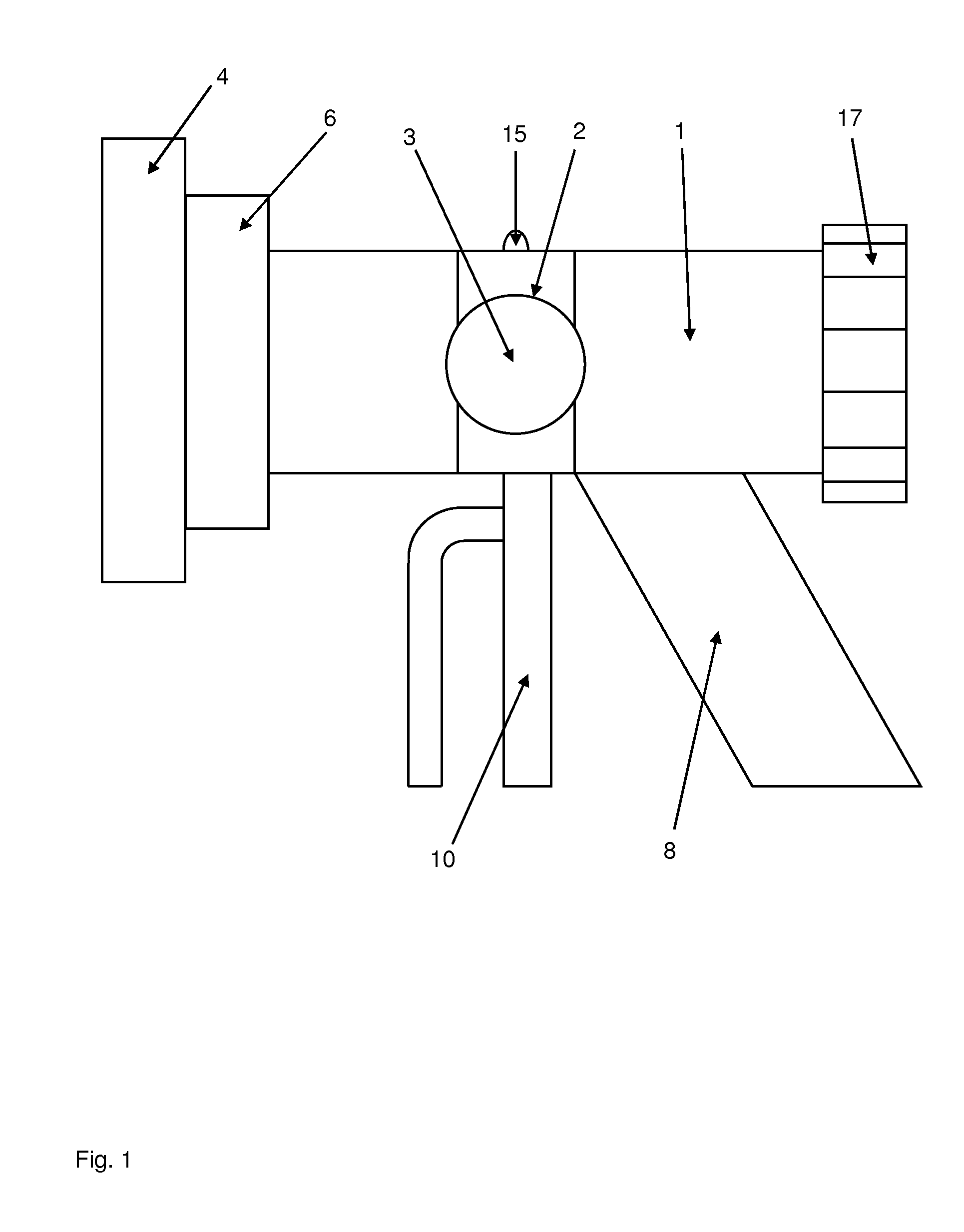
[0055]FIG. 1 shows a top view onto the side of a dispensing device according to the invention having a cylinder-shaped base body (1), in which a lateral opening (2) is provided in the form of a bore hole. A valve body (3) having cylindrical geometry is situated in the opening (2) and is mounted such as to be rotatable in the opening (2) and forms a valve together with passages in the valve body (3) and in the base body (1) such that at least two different passages through the valve body (3) and the base body (1) are opened in two different positions of the valve body (3), whereas the other passages are closed. The shape of the valve body (3) is adapted to the shape of the opening (2) in a manner such that the walls of the valve body (3) end in a sealed manner against the opening (2).

[0056]A first cartridge connector (4) having a large diameter and a second cartridge connector (6) having a smaller diameter are arranged on the front side (on the left in FIG. 1) of the dispensing devic...


PUM


Abstract

A dispensing device for cartridges having a trigger grip for operating a valve of the dispensing device, a connection for supplying a pressurized gas, a cartridge connector for connecting a cartridge, and a base body, in which at least one passage extends through such that pressurized gas can be guided to the cartridge connector. The cartridge connector comprises an opening towards the passage such that the content can be expelled from the cartridge upon application of the pressurized gas to the floor of a cartridge when the cartridge is arranged in the cartridge connector, and wherein the passage can be closed and opened through the operated valve. The valve has a valve body that is arranged in the base body in a rotatable manner, wherein a motion of the trigger grip leads to a rotation of the valve body in the base body. The passage is arranged in or on the valve body such that the passage is closed in a first position of the valve body and the passage in or on the valve body guides the pressurized gas to the cartridge connector in a second position of the valve body.

Description

[0001]The present invention relates to a dispensing device for cartridges comprising a trigger grip for operating a valve of the dispensing device, a connection for supplying a pressurised gas, a cartridge connector for connecting a cartridge, and a base body, in which at least one passage extends through which the pressurised gas can be guided to the cartridge connector, whereby the cartridge connector comprises an opening towards the passage such that the content can be expelled from the cartridge upon application of the pressurised gas to the floor of a cartridge that is arranged in the cartridge connector, and whereby the passage can be closed and opened through the operated valve.[0002]Accordingly, the subject matter of the invention is a dispensing device for squeezing out flowable materials from cartridges. The dispensing device is intended, in particular, for the dispensing of bone cements. It has been known for decades to squeeze out cartridges through the use of compressed...

Claims


Application Information

Patent Timeline
Patent Type & Authority Patents(United States)
IPC IPC(8): B65D83/64A61B17/00A61B17/88B05C17/015F16N11/10
CPCB05C17/015A61B17/8822A61B17/8825A61B17/8827F16N11/10A61B2017/0023
Inventor VOGT, SEBASTIANBUCHNER, HUBERT
Owner HERAEUS MEDICAL
Why Eureka
Try Eureka