Apparatus and method for determining shape of end of welding bead

a technology of end and end, which is applied in the direction of laser beam welding apparatus, manufacturing tools, instruments, etc., can solve the problems of reducing production efficiency, increasing the cost of the apparatus, and the end of the welding bead cannot be determined, so as to achieve high-speed recognition processing, high accuracy, and the effect of enabling high-speed determination processing

Inactive Publication Date: 2015-02-03
SUZUKI MOTOR CORP
View PDF29 Cites 55 Cited by
  • Summary
  • Abstract
  • Description
  • Claims
  • Application Information

AI Technical Summary

Benefits of technology

[0013]The present invention was made in consideration of the foregoing problems. It is an object of the present invention to provide an apparatus and a method for determining the shape of the end of a welding bead, which are capable of capturing an image of a welding bead region at the same time as a welding process, and determining a hole defect at the end of the bead with high accuracy within a very short period of time immediately after the welding process.
[0014]The inventors of the present application have found that a certain amount of metal thermoluminescence can be observed from the weld material while overcoming the low transmittance of the welding laser emitting unit immediately after the completion of the welding process. As a result, the inventors have discovered a method of capturing the image with a camera and the like, and utilizing the images for determination of a hole defect. In the conventional method disclosed in Patent Document 1, this image is considered unnecessary since it is the one after the welding process. The inventors of the present application have established an apparatus and a method capable of carrying out examination of a hole defect within a very short period of time after the welding process (substantially, within the welding process time), paying attention to the image immediately after the completion of the welding process and performing characteristic shape determination which was not known before.

Problems solved by technology

For this reason, there is a problem that a weld defect at the end of the bead region cannot be determined with the same determination method as that used during the welding process.
Moreover, the method disclosed in Patent Document 2 also requires an apparatus for emitting a measuring laser in addition to the welding laser, leading to a problem of increasing the cost of the apparatus.
However, this method has a problem of reduction in production efficiency since the examination process is added as an extra step after the welding is completed.

Method used


Image

  • Apparatus and method for determining shape of end of welding bead
  • Apparatus and method for determining shape of end of welding bead
  • Apparatus and method for determining shape of end of welding bead

Examples


Embodiment Construction

[0051]With reference to the drawings, description is given below of an apparatus and a method for determining the shape of an end of a welding bead part (hereinafter referred to as the “bead”) according to an embodiment of the present invention.

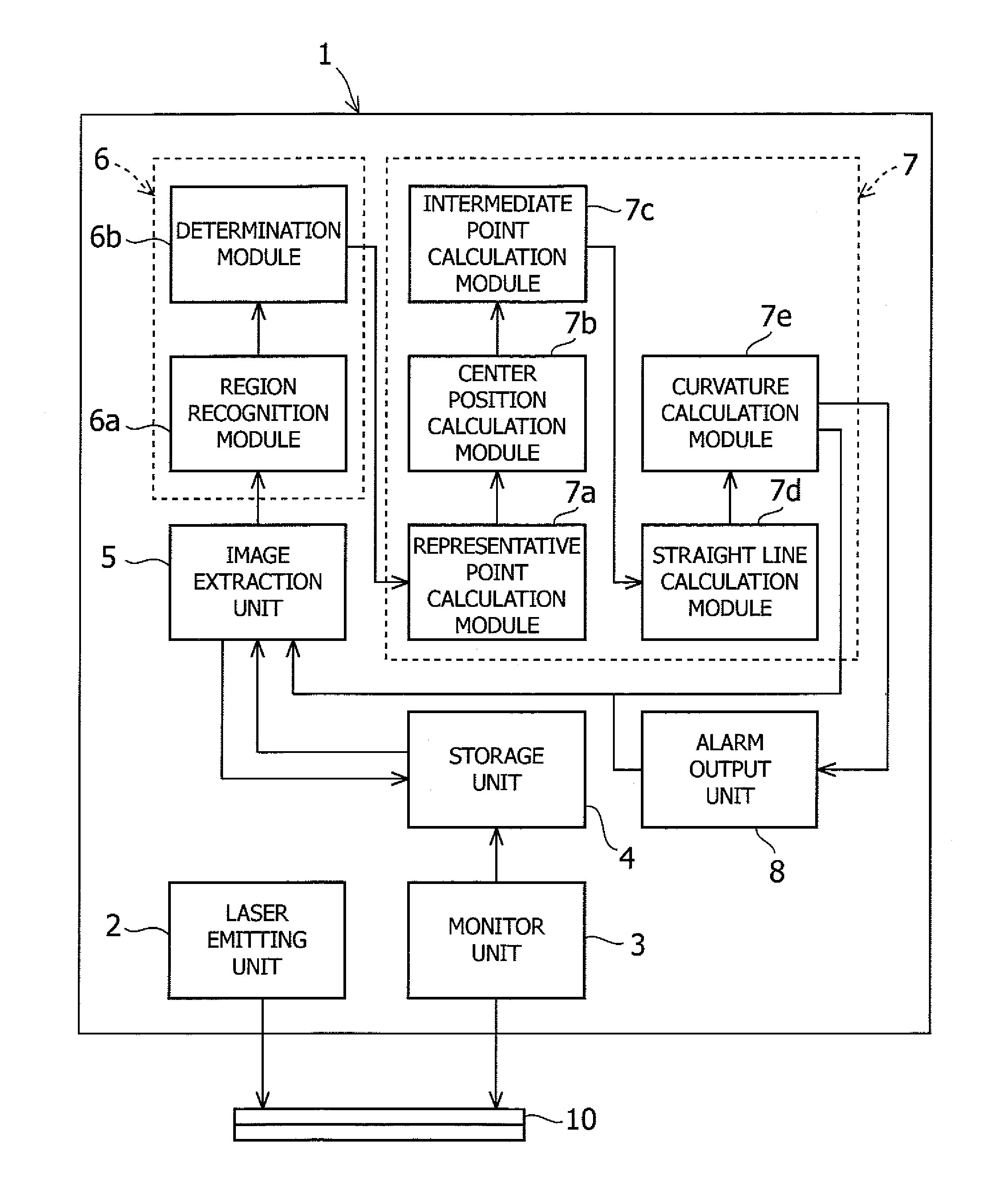
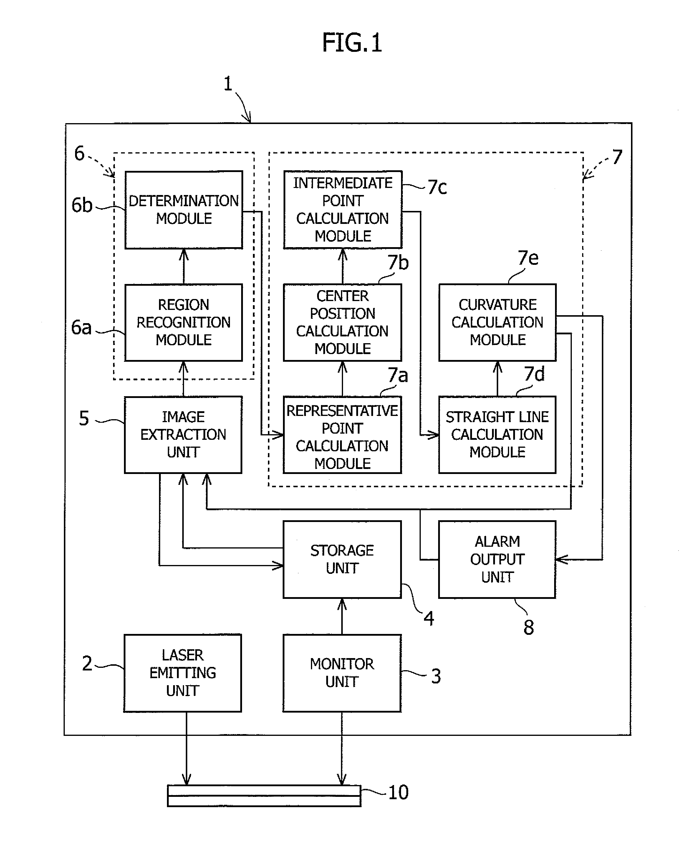
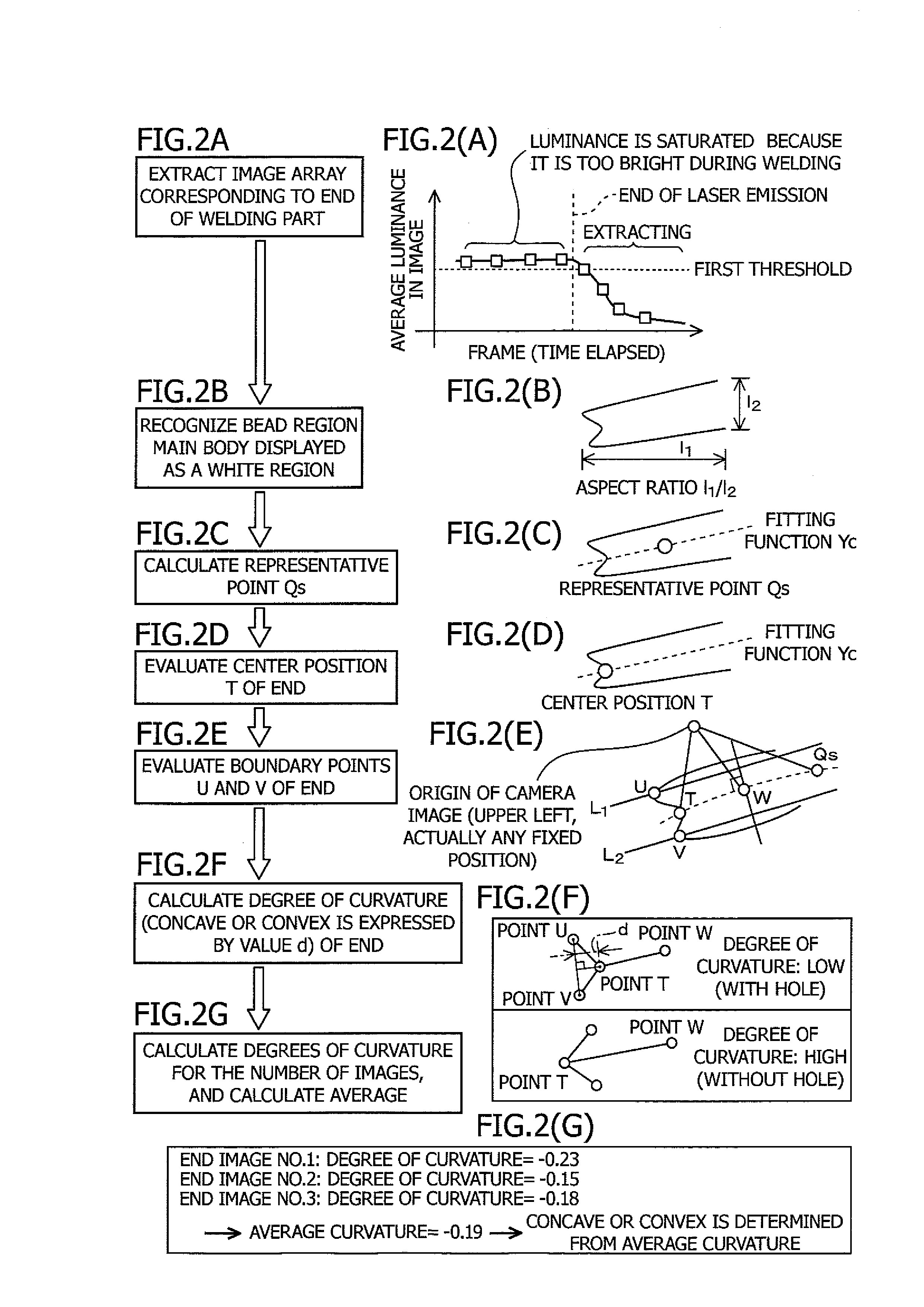
[0052]FIG. 1 is a block diagram showing a configuration of an apparatus for determining the shape of an end of a welding bead according to an embodiment of the present invention, and FIG. 2 is a diagram showing a procedure for determining the shape of the end of a welding bead region. FIG. 3 is a diagram showing a configuration of a monitor unit according to the embodiment of the present invention, and an image extracting process performed by an image extraction unit.

[0053]As shown in FIG. 1, an apparatus 1 for determining the shape of the end of the bead according to this embodiment is an apparatus used for lap welding weld materials 10. The apparatus 1 includes a laser emitting unit 2, a monitor unit 3, a storage unit 4, an image extraction...


PUM

PropertyMeasurementUnit
wavelengthaaaaaaaaaa
timeaaaaaaaaaa
shapeaaaaaaaaaa

Abstract

An apparatus 1 of the present invention includes a laser emitting unit 2, a monitor unit 3, a storage unit 4, an image extraction unit 5, a bead recognition unit 6, and a bead shape determination unit 7. The bead shape determination unit 7 is configured to calculate the position of the end of a bead region based on the bead region recognized by the bead recognition unit 6, and to determine whether the shape of the end of the bead region is convex or concave in the extending direction of the bead region.

Description

CROSS-REFERENCE TO RELATED APPLICATIONS[0001]This application claims the benefit of the filing date of Japanese Patent Application No. 2010-192129 filed Aug. 30, 2010, the entire disclosure of which is hereby incorporated herein by reference.BACKGROUND OF THE INVENTION[0002]1. Field of the Invention[0003]The present invention relates to an apparatus and to a method for determining the shape of an end of a welding bead (welding part) formed by irradiating a welding material with a welding laser. More specifically, the present invention relates to an algorithm to, in laser lap welding, capture an image of an end of a welding bead with a high-speed camera and to determine whether there is a hole defect at the end of the welding bead based on the captured image in a very short period of time immediately after the welding and before thermoluminescence from the metal ends disappears.[0004]2. Description of Related Art[0005]There has heretofore been proposed a method for detecting a weld d...

Claims


Application Information

Patent Timeline
Patent Type & Authority Patents(United States)
IPC IPC(8): B23K26/03B23K26/21B23K26/00B23K26/24B23K31/00B23K31/12G01B11/24
CPCB23K26/246B23K26/032B23K31/125B23K26/244
Inventor ISHIDA, HIDENOBUOZAWA, NAOKIHAGIHARA, TSUKASAUSUI, SHUICHI
Owner SUZUKI MOTOR CORP
Why Eureka
Try Eureka