Multiple gas turbine forwarding system

a gas turbine and forwarding system technology, applied in the direction of machine/engine, service pipe system, positive displacement liquid engine, etc., can solve the problems of cost and space prohibitive use of the forwarding skid existing

Active Publication Date: 2015-02-10
GE INFRASTRUCTURE TECH INT LLC
View PDF15 Cites 88 Cited by
  • Summary
  • Abstract
  • Description
  • Claims
  • Application Information

AI Technical Summary

Problems solved by technology

Accordingly, for multiple-turbine arrangements, use of this existing forwarding skid is both cost prohibitive and space prohibitive.

Method used


Image

  • Multiple gas turbine forwarding system
  • Multiple gas turbine forwarding system
  • Multiple gas turbine forwarding system

Examples


first embodiment

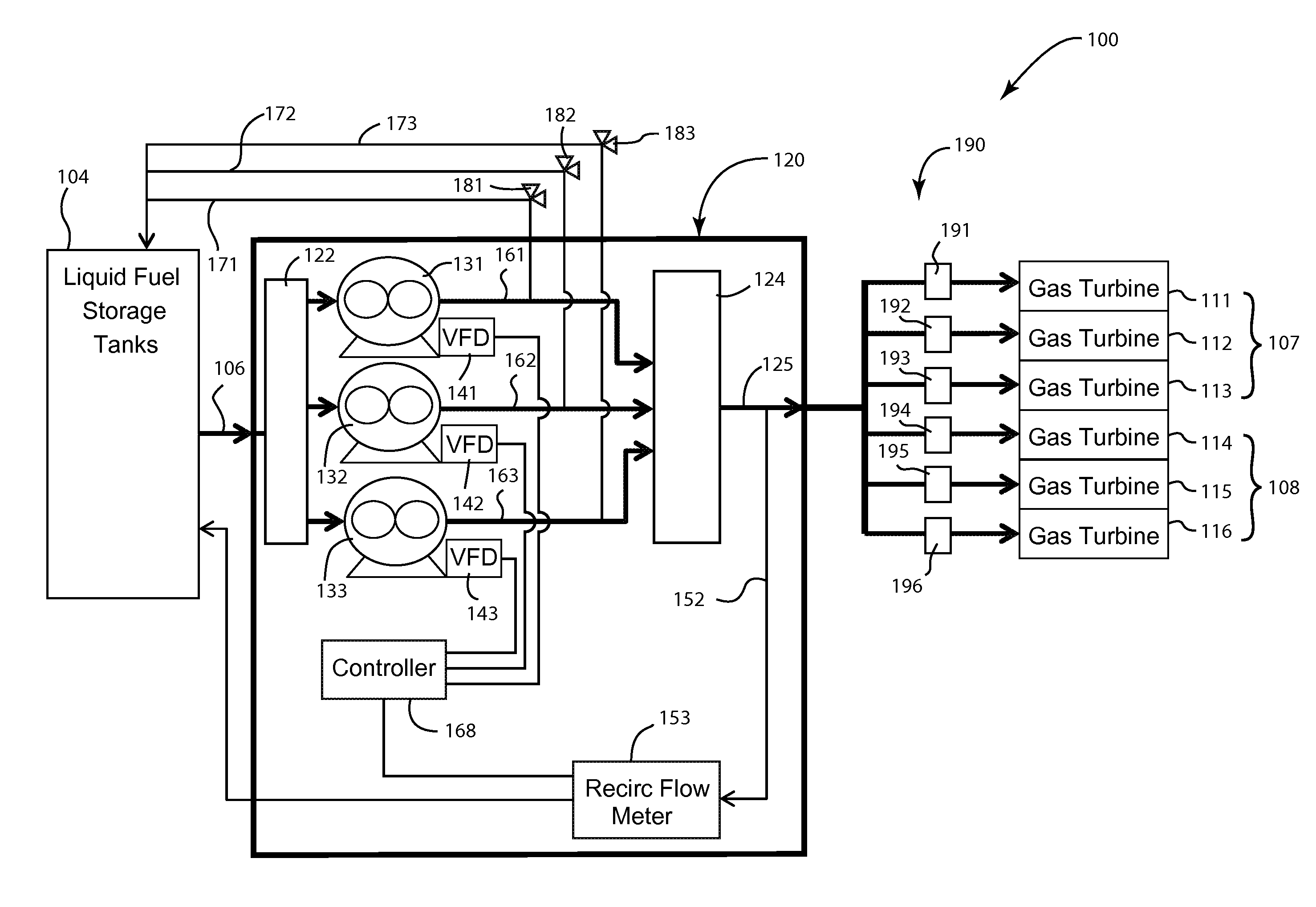
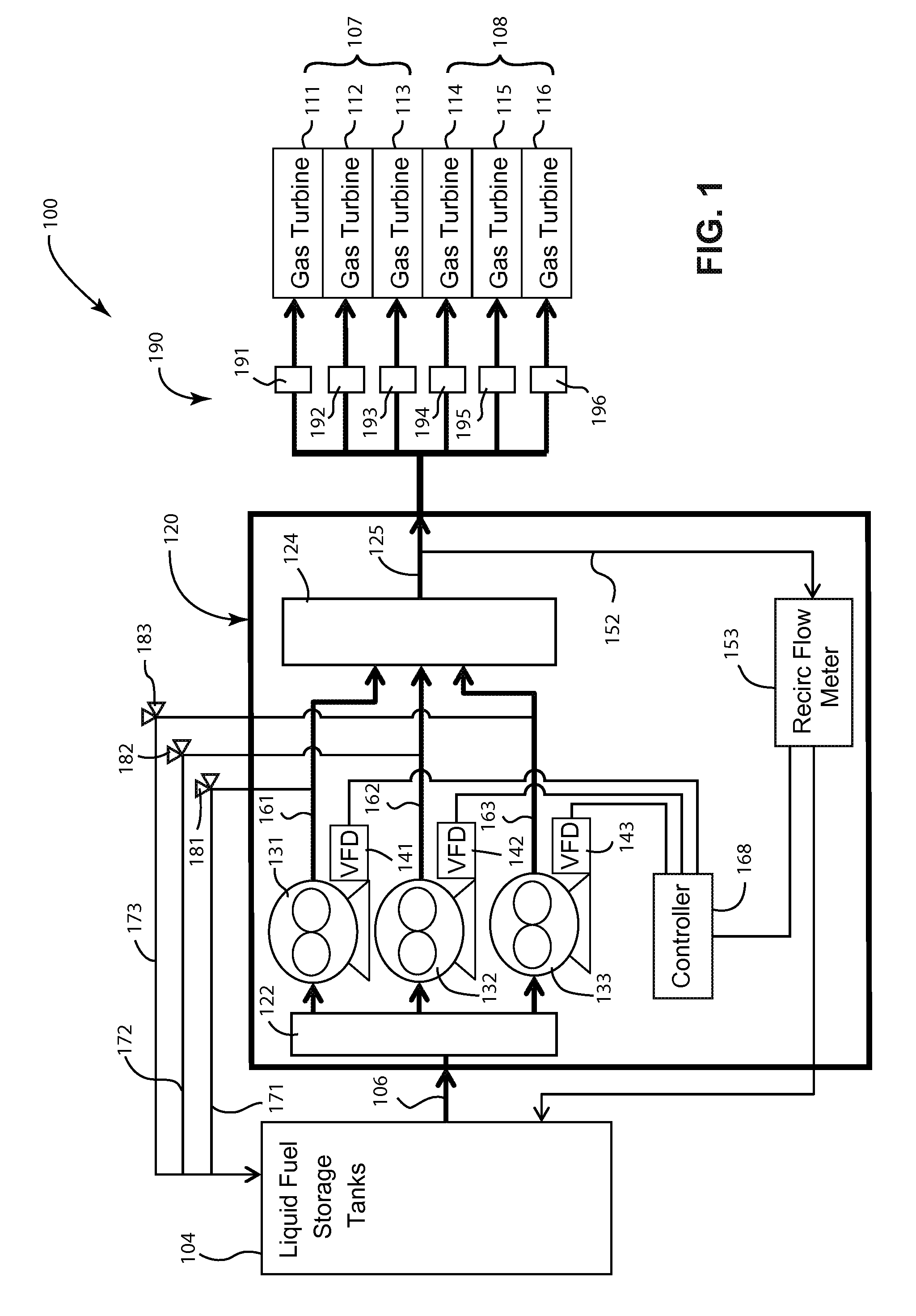
[0015]In the gas turbine fuel forwarding system, the skid 120 includes an inlet manifold 122 for receiving fuel from the storage tanks 104 and an outlet manifold 124 for delivering the fuel to the turbines via a skid outlet line 125.

[0016]A group of pumps is configured to receive fuel from the inlet manifold 122 and deliver the fuel via pump lines 161, 162, 163 to the outlet manifold 124. First and second pumps 131, 132 are sufficient to meet the demands of the plurality of turbines 111 to 116. However, a backup pump 133 is provided and called into action in the event of a failure or other malfunction of the first or second pumps 131, 132. The pumps 131, 132, 133 are positive displacement pumps. Although, it is possible that another type of pump may be used as long as the pump's output can be adjusted in a predictable manner. A suitable positive displacement pump is the 3-screw pump.

[0017]Safety lines 171, 172, 173 respectively connect the pump lines 161, 162, 163 to the storage tan...

second embodiment

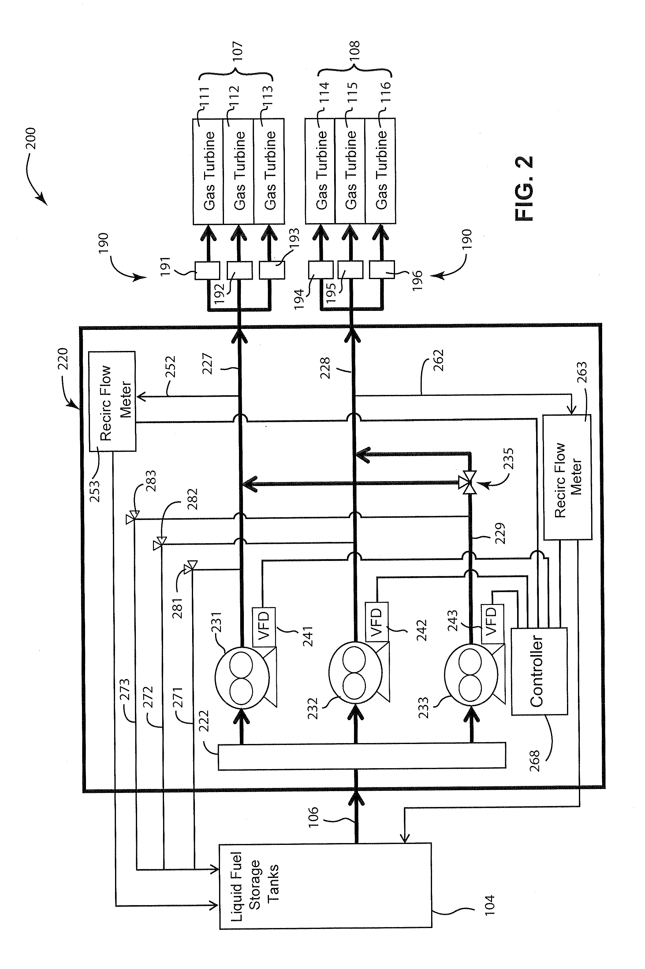
[0021]Referring to FIG. 2, the gas turbine fuel forwarding system 200 will be described. The gas turbine fuel forwarding system 200 is similar to the gas turbine fuel forwarding system 100; however, the skid 220 of the gas turbine fuel forwarding system 200 includes a pump and recirculation line arrangement that is different from the skid 120.

[0022]The skid 220 includes an inlet manifold 222 for receiving fuel from the storage tanks 104 and first and second skid outlet lines 227, 228 for delivering the fuel to the turbines 111 to 116.

[0023]A first pump 231 and a second pump 232 are configured to receive fuel from the inlet manifold 222 and respectively deliver the fuel to the first and second skid outlet lines 227, 228. As shown in FIG. 2, the first skid outlet line 227 is dedicated to the first group of turbines 107 and the second skid outline line 228 is dedicated to the second group of turbines 108. As such, the first pump 231 has a capacity that sufficiently meets the demand of ...


PUM


Abstract

A fuel forwarding skid for delivering fuel from a storage area to a plurality of turbines includes at least two pumps for delivering fuel to a skid outlet line. A flow control device is connected to the pumps to control an output of the pumps. A recirculation line is in communication with the skid outlet line and is adapted to return a portion of the fuel in the skid outlet line to the storage area. A flow meter is in communication with the recirculation line to measure a rate of flow in the recirculation line, and the flow control device controls the output of at least one of the pumps in accordance with the rate of flow in the recirculation line.

Description

FIELD OF THE INVENTION[0001]The present technology relates generally to fuel supply systems and more particularly to fuel forwarding systems for multiple gas turbines.BACKGROUND OF THE INVENTION[0002]A system for providing liquid fuel to a gas turbine may include a forwarding skid arranged to deliver the fuel from storage tanks to the turbine. A multiple turbine arrangement may require a plurality of such skids sufficient to meet the fuel demands of the various turbines.[0003]An existing forwarding skid known to applicants includes a two-pump arrangement having a capacity to supply fuel to only one turbine. Accordingly, with this skid configuration, a total of six forwarding skids would be required to supply a six-turbine system. The addition of each forwarding skid also requires additional piping, connections and devices.[0004]Each forwarding skid has an inlet connected to the fuel storage tanks and an outlet to a respective turbine, thereby requiring separate piping for each addit...

Claims


Application Information

Patent Timeline
Patent Type & Authority Patents(United States)
IPC IPC(8): F02C7/236
CPCF02C7/236F02C7/22F02C9/36F05D2240/40Y10T137/85954Y10T137/86163Y10T137/0324Y10T137/85978
Inventor HAINS, JOHN VICTORMOBLEY, GARY CLETUSGUPTA, ABHIJIT
Owner GE INFRASTRUCTURE TECH INT LLC
Why Eureka
Try Eureka