
Method for symbol sampling in a high time delay spread interference environment

a high-time delay spread and interference environment technology, applied in the field of radio communications, can solve the problems of affecting the initial synchronization and call start time, the bit-error rate (ber) of the receive radio in the site overlap area, and the conventional synchronization method takes a relatively long time to converge to the optimal synchronization time,

Active Publication Date: 2015-02-10
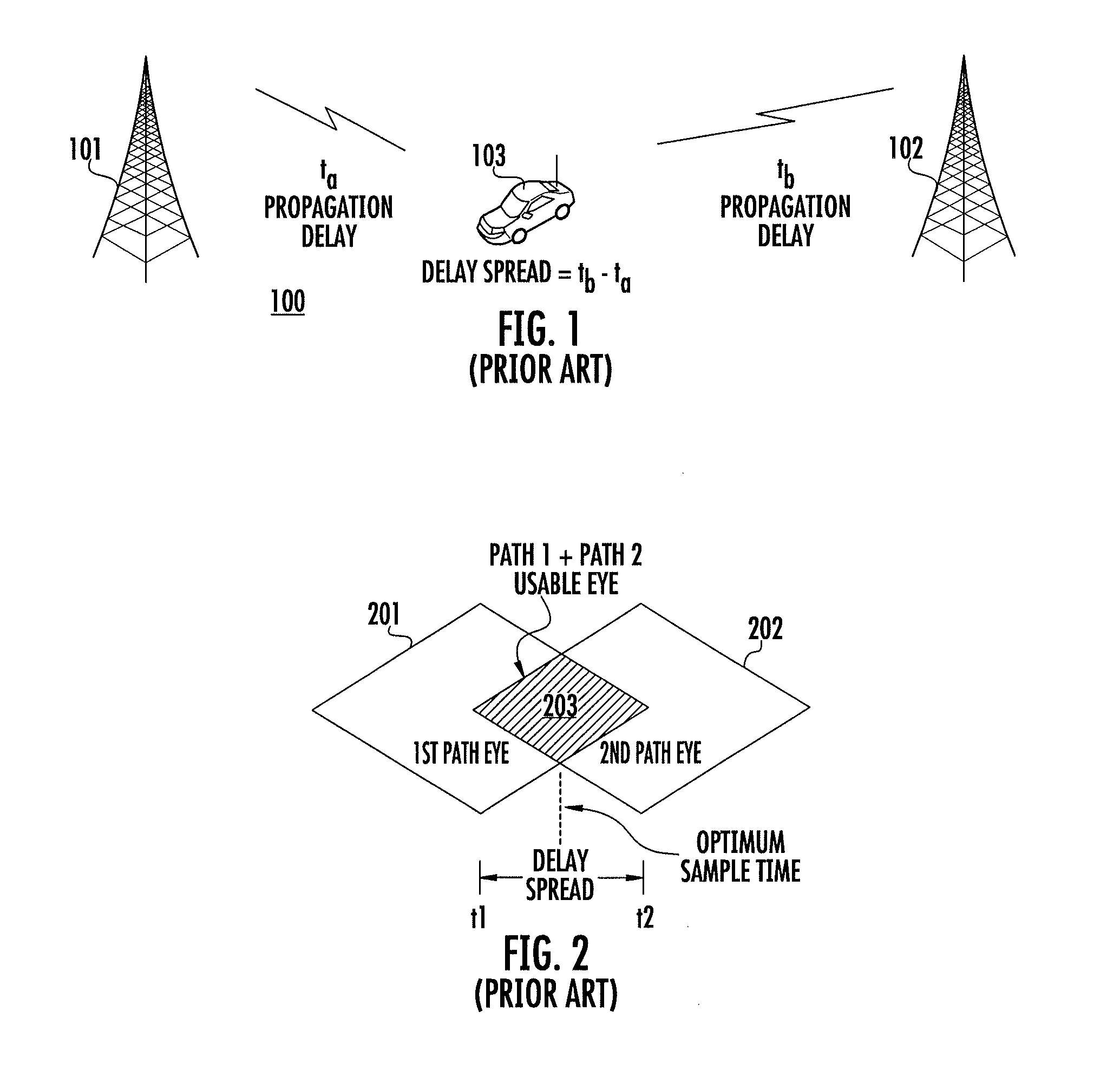
HARRIS CORP
View PDF5 Cites 4 Cited by
  • Summary
  • Abstract
  • Description
  • Claims
  • Application Information

AI Technical Summary

Benefits of technology

The invention is about a method for sampling symbols in a digital communication system. It involves acquiring a time-varying baseband waveform and sampling it at a rate called the oversample rate. During an evaluation time, an error value is calculated for each sample, which is the average distance between the measured waveform and the closest known symbol value. An optimal sample time is then determined based on these error values. The invention also includes a radio frequency communication device that includes an RF receiver and an electronic circuit that samples the waveform and calculates error values for each sample. This optimal sample time is then determined based on the calculated error values. The technical effect of this invention is to improve the accuracy and reliability of symbol sampling in a digital communication system.

Problems solved by technology

The delay spread is known to degrade the bit-error-rate (BER) of receive radios in site overlap areas.
The symbols contained in the synchronization field do not represent user data and therefore comprise overhead in the communication system.
Still, due to the limited number of synchronization symbols, conventional synchronization methods take a relatively long time to converge to the optimal synchronization time when operating in a high delay spread environment.
This slow synchronization process can severely degrade the time required to establish initial synchronization and call start.

Method used


Image

  • Method for symbol sampling in a high time delay spread interference environment
  • Method for symbol sampling in a high time delay spread interference environment
  • Method for symbol sampling in a high time delay spread interference environment

Examples


Embodiment Construction

[0029]The invention is described with reference to the attached figures. The figures are not drawn to scale and they are provided merely to illustrate the invention. Several aspects of the invention are described below with reference to example applications for illustration. It should be understood that numerous specific details, relationships, and methods are set forth to provide a full understanding of the invention. One having ordinary skill in the relevant art, however, will readily recognize that the invention can be practiced without one or more of the specific details or with other methods. In other instances, well-known structures or operation are not shown in detail to avoid obscuring the invention. The invention is not limited by the illustrated ordering of acts or events, as some acts may occur in different orders and / or concurrently with other acts or events. Furthermore, not all illustrated acts or events are required to implement a methodology in accordance with the in...


PUM


Abstract

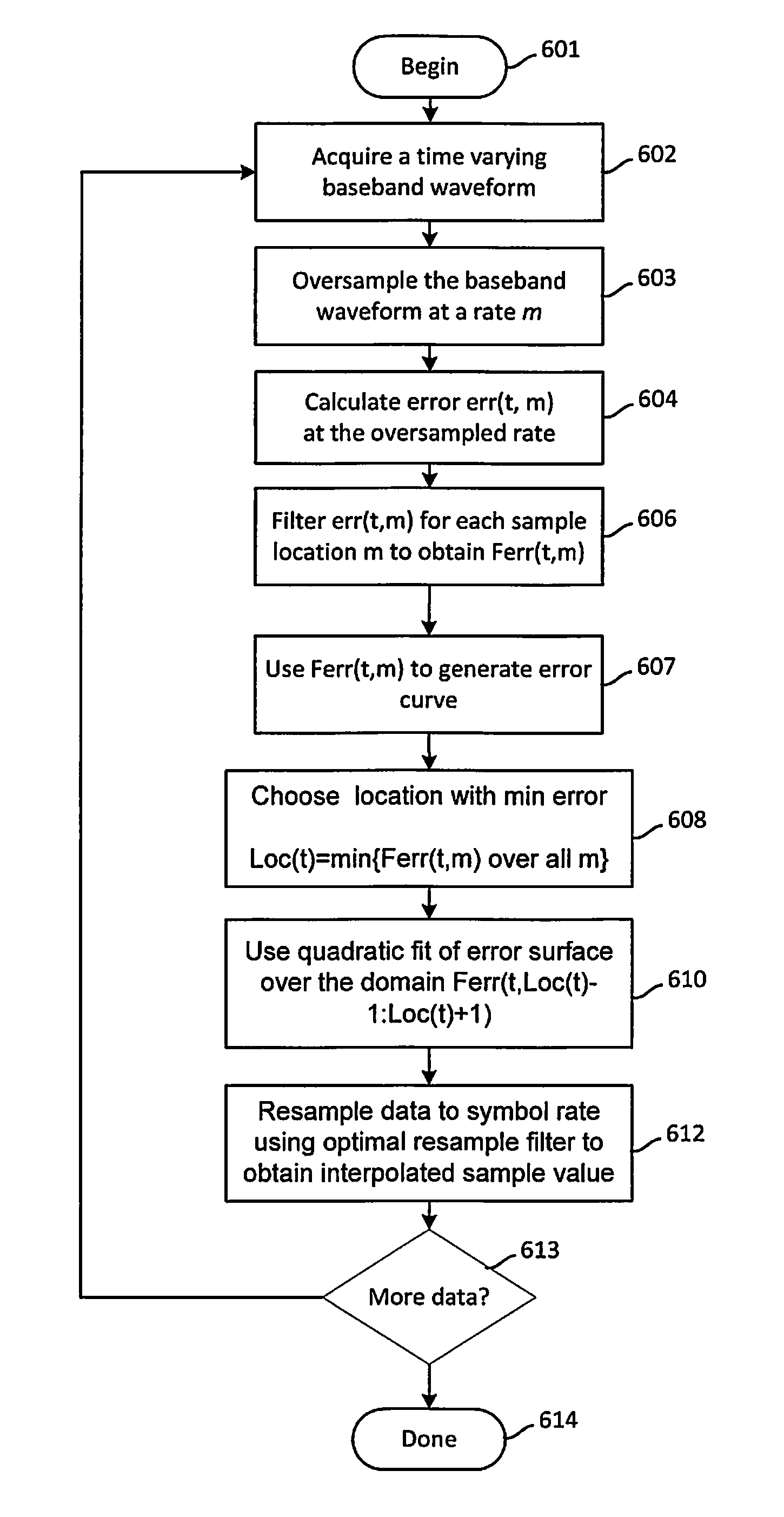
Symbol sampling in a high time delay spread interference environment includes acquiring (602) a time varying baseband waveform. The waveform has a signal amplitude that varies between one of a plurality of symbol states. The waveform is sampled (603) at a rate of m times the symbol rate. During an evaluation time, an error value is calculated (604, 606) for each of m data sample positions. Each of the error values comprises an average distance between the measured value of the waveform as indicated by the data sample and a closest known symbol value. The error values are used to create an error surface. Thereafter, the error surface is modeled as a quadratic and an optimal sample time is determined (608, 610, 612) based on finding the time location where the quadratic surface is minimum. A sinc interpolator is then used to resample the data.

Description

BACKGROUND OF THE INVENTION[0001]1. Statement of the Technical Field[0002]The inventive arrangements relate to radio communications and more particularly to improvements in symbol sampling in communications environments where a significant amount of delay spread exists.[0003]2. Description of the Related Art[0004]Simulcast systems create delay spread at receive sites that is proportional to site spacing. The delay spread is known to degrade the bit-error-rate (BER) of receive radios in site overlap areas. Coverage area of a simulcast system can be improved by reducing the adverse effects that delay spread has upon BER. When the coverage area is improved in this way, the number of simulcast transmitter sites can be reduced, thereby lowering overall infrastructure costs.[0005]Symbol synchronization is used to estimate the optimal time for sampling each symbol in a received signal. Improved symbol synchronization is a key factor for purposes of reducing BER. Conventional synchronizatio...

Claims


Application Information

Patent Timeline
IPC IPC(8): H04L7/00
CPCH04L7/0029H04L7/0062
Inventor HARTLESS, MAC L.TAYLOR, RICHARD D.WYNN, STEVE R.
Owner HARRIS CORP
Learn More