Method and apparatus for synchronization of the OFDM systems

a technology synchronization, applied in the field of synchronization of orthogonal frequency division multiplexing (ofdm) systems, can solve the problems of severe inter-symbol interference, inefficient transmission of high-rate data for using this type of communication system, and inability to meet the needs of high data ra

Active Publication Date: 2005-05-19
IND TECH RES INST
View PDF9 Cites 37 Cited by
  • Summary
  • Abstract
  • Description
  • Claims
  • Application Information

AI Technical Summary

Benefits of technology

[0013] The present invention overcomes the disadvantages of the aforementioned conventional OFDM systems. The first object of the present invention is to provide a synchronization method and an apparatus for an OFDM system. The present invention uses the cyclic prefix characteristics of the guard intervals as the basis, and uses the delay conjugate multiplication module, phase differential operation, symbol-by-symbol average operation and edge detection to estimate the location of the entire ISI-free region. For a multi-path channel with large delay spread, the present method performs well and it is more suitable for the broadcasting system, such as DAB and DVB-T systems.
[0015] As shown in FIG. 3, the first part is performing the delay conjugate multiplication module for the received signals, passing through the first symbol-by-symbol average operation, and taking the normalized phase to obtain the output signal θ1(n). The delay conjugate multiplication module is based on the cyclic prefix characteristics of the guard interval and the first symbol-by-symbol average operation is used to reduce the noise effects.
[0016] The phase processor of the second part includes performing the phase differential operation, taking the absolute value and then passing through the second symbol-by-symbol average operation. The object of the phase processor is used to obtain a feature signal θ4(n) that can indicate the location of the ISI-free region, and the second symbol-by-symbol average operation is used to reduce the channel fading effects.

Problems solved by technology

Conventional single-carrier transmission technologies, such as GSM, cannot meet the needs of high data rate.
This is because the signal sampling period becomes very short under the high data rate transmission, it is therefore easily affected by the channel delay spread and leads to severe inter-symbol interferences (ISI).
For the complexity of the receivers, it is inefficient to transmit high-rate data for using this type of communication system.
However, the multiple-carrier technologies have three major disadvantages that prevent the technologies from wide use.
This leads to a waste of bandwidth.
This will lead to non-linear distortion when passing the power amplifier during the transmission.
Due to the progress of digital signal processing (DSP) and VLSI in recent years, the difficult resulted from computation complexity is improved.
In addition to the aforementioned non-linear distortion caused by the large PAPR, the use of orthogonality in the FFT-based OFDM technology also increases the sensitivity to the signal synchronization errors.
As the carrier frequency offset increases, the orthogonality will be damaged and the system performance will rapidly deteriorate.
However, if the channel delay spread is close to the length of a guard interval, the ISI effects due to the imprecision of the rough symbol timing estimation is significant.
Besides, it will lead to the larger imprecision of the subsequent carrier frequency offset detection.
On the other hand, the packet switch network does not transmit the continuous data, and sometimes the data may be even bursty.
It is more suitable for white gauss noise channel, but it is not suitable for a multi-path channel with large delay spread.
This method is suitable for a multi-path channel with larger delay spread to estimate the location of one point in the ISI-free region, but it is not suitable to estimate the location of the entire ISI-free region.
However, it is more difficult to determine the value of a fixed optimal threshold to separate the ISI-free region, and it needs more computation complexity to implement.

Method used


Image

  • Method and apparatus for synchronization of the OFDM systems
  • Method and apparatus for synchronization of the OFDM systems
  • Method and apparatus for synchronization of the OFDM systems

Examples


Embodiment Construction

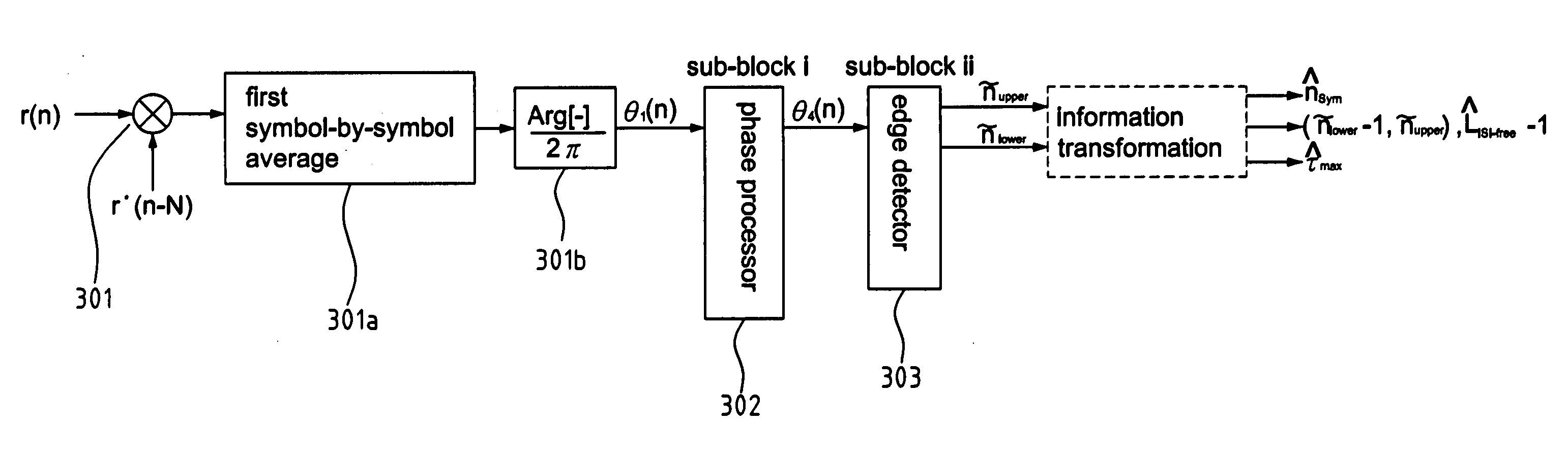
[0034]FIG. 3 is a block diagram of the synchronization method and apparatus for the OFDM system. As shown in FIG. 3, the method can be divided into three major parts: delay conjugate multiplication module 301, phase processor 302 and edge detector 303.

[0035] The first part is to perform the delay conjugate multiplication module for the received signal r(n), pass through the first symbol-by-symbol average operation 301a, and use a phase calculator 301b to obtain the normalized phase signal θ1(n). The delay conjugate multiplication module that calculates the product of the received signal and its N-sample-delayed and conjugate version is based on the cyclic prefix characteristic of the guard interval. The symbol-by-symbol average operation 301a is used to reduce the noise effects. The symbol-by-symbol average operation 301a, the cyclic prefix characteristics of the guard interval, and the definition of ISI-free region will be described as below.

[0036] Based on the present invention,...


PUM


Abstract

A method and apparatus for the signal synchronization of an OFDM system are proposed including a delay conjugate multiplication module, a phase processor and an edge detector. It provides estimates for the boundaries of ISI-free region by utilizing the characteristics of the guard interval and combining the techniques of the delay conjugate multiplication module, phase differential operation, symbol-by-symbol average operation, and edge detection. This method provides an improved performance in a multi-path fading channel with large delay spread, and can be utilized in a broadcasting system, such as the DAB and DVB-T systems. This invention is easy to determine a fixed optimal threshold that can directly separate the ISI region in any mobile environment, thereby most symbol information with ISI-free version can be obtained.

Description

FIELD OF THE INVENTION [0001] The present invention generally relates to the transmission of an orthogonal frequency division multiplexing (OFDM) system, and more specifically to a method and an apparatus for the synchronization of the OFDM systems. BACKGROUND OF THE INVENTION [0002] The high data rate transmission is one of the major features of the present-day wireless communication systems. Conventional single-carrier transmission technologies, such as GSM, cannot meet the needs of high data rate. This is because the signal sampling period becomes very short under the high data rate transmission, it is therefore easily affected by the channel delay spread and leads to severe inter-symbol interferences (ISI). From the frequency's point of view, the signal bandwidth of high data rate transmission is large, and in comparison to the coherent bandwidth of the channel, the signal is apparently influenced by the frequency selective fading effect of the channel. Consequently, when using ...

Claims


Application Information

Patent Timeline
Patent Type & Authority Applications(United States)
IPC IPC(8): H04H1/00H04H20/72H04H40/27H04J11/00H04L7/02H04L27/26
CPCH04H20/72H04L27/2678H04L27/2662H04H40/27
Inventor SHEU, CHORNG-RENCHANG, MENG-CHUNHUANG, CHIA-CHICHANG, YU-JUNG
Owner IND TECH RES INST
Why Eureka
Try Eureka