Solar panel attachment system for a roof

a solar panel and roof technology, applied in the field of solar panel attachment systems for roofs of buildings, can solve the problems of inconsistent installation torque values, installation of bolt arrangements that take considerable time to install, and installation of installers to juggle many, so as to achieve quick and easy attachment to the roof of the building, the effect of easy installation

Inactive Publication Date: 2015-02-17
A RAYMOND & CO
View PDF128 Cites 17 Cited by
  • Summary
  • Abstract
  • Description
  • Claims
  • Application Information

AI Technical Summary

Benefits of technology

[0005]The present attachment system is advantagous over traditional devices. For example, in one aspect, a single motion installation is employed to engage an auxiliary roof component, such as a solar panel, for latch engagement without requiring tools. In an aspect of the present attachment system, an auxiliary roof component is quickly and easily secured to a building roof in a fast manner without requiring the installer to juggle multiple parts. In another aspect, a striker or protruding member is preassembled directly to a glass surface of a solar panel and a latch assembly is preassembled to a building roof via an easy to install roof clamp, prior to assembly of the solar panel to the latch assembly. Moreover, the auxiliary roof component can be easily detached from the latch assembly in an aspect of the present system. Another aspect allows for quick connect mounting of the auxiliary roof component to a latch assembly coupled to a tilted frame and / or by use of ballast on a horizontal surface. Another aspect of the present system is advantageous over conventional devices since this aspect uses lightweight and strong composite materials for various components of the attachment system. When installed, the latch assembly and roof clamp can optionally provide an electrical grounding path between the auxiliary roof component and the metal roof, or wires attached thereto. Additional advantageous and features of the present invention will become apparent in the following description and appended claims, taking in conjunction with the accompanying drawings.

Problems solved by technology

Such conventional methods cause the installer to juggle many loose fasteners while simultaneously holding heavy solar panels and / or roof mounting components, often on a tilted metal roof in unpleasant weather conditions.
Furthermore, such traditional multi-piece screw or bolt arrangements take considerable time to install while also having inconsistent installation torque values, especially in the common situation where many of these solar panel mounting devices are required for each roof.

Method used


Image

  • Solar panel attachment system for a roof
  • Solar panel attachment system for a roof
  • Solar panel attachment system for a roof

Examples


Embodiment Construction

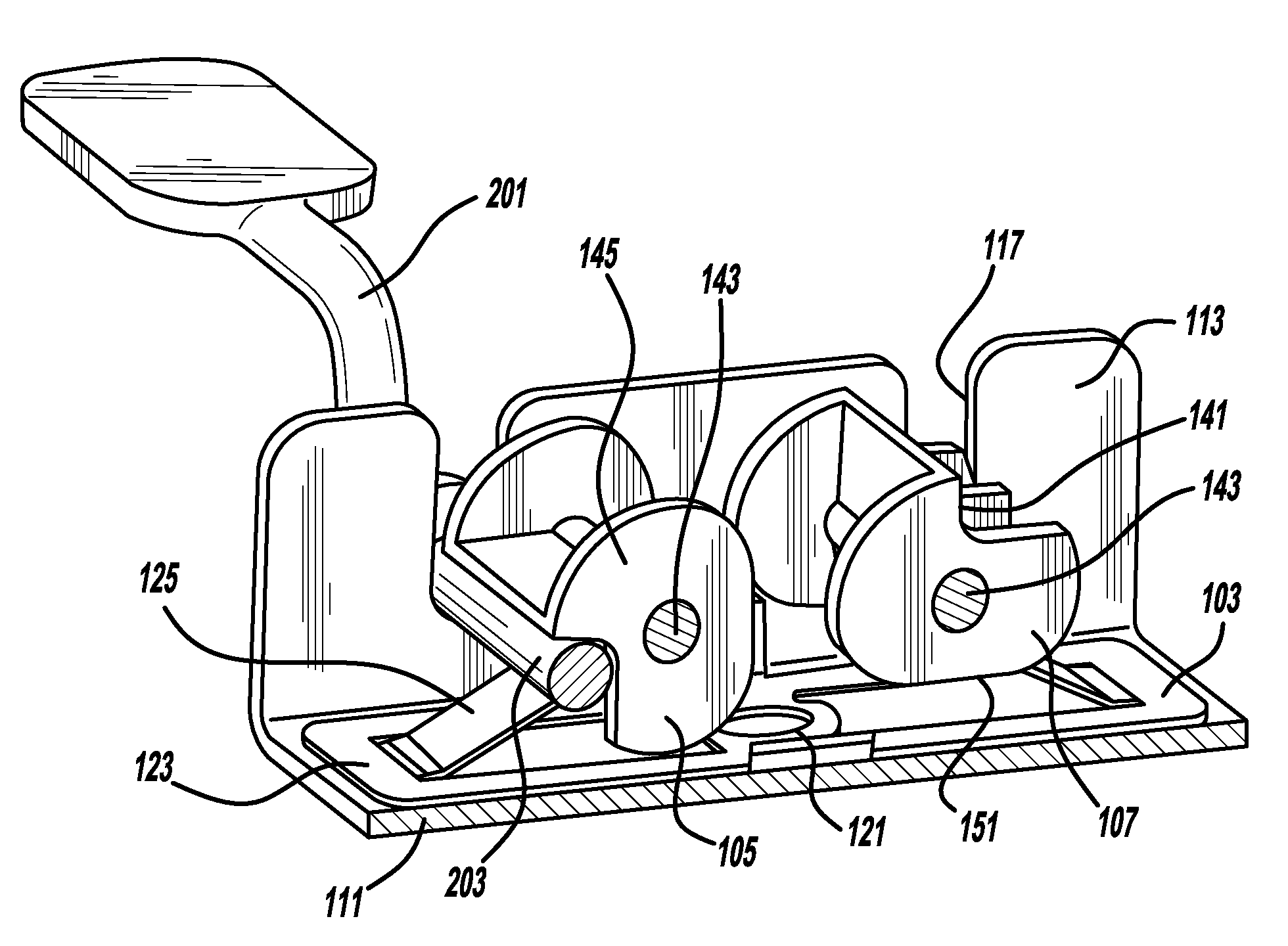
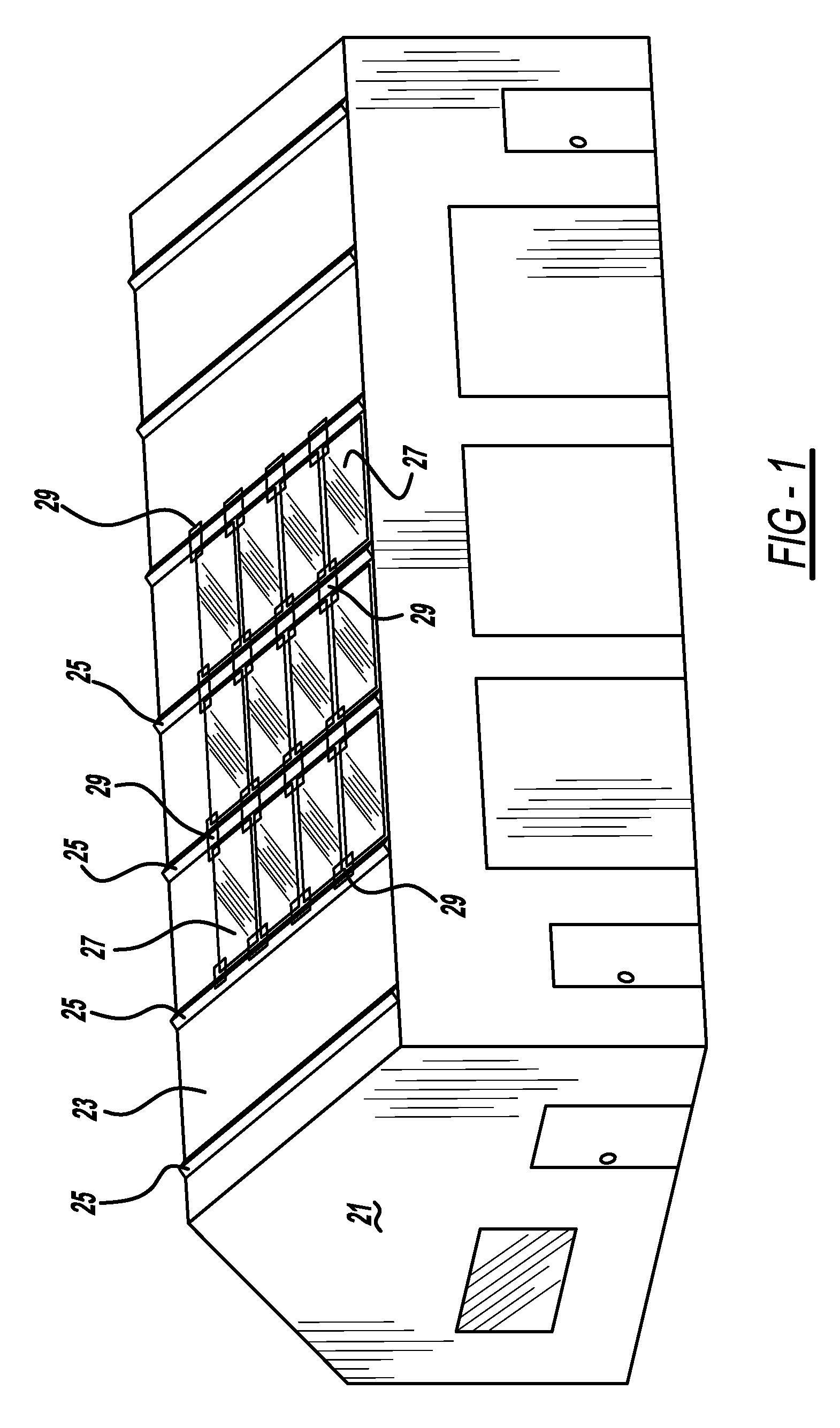
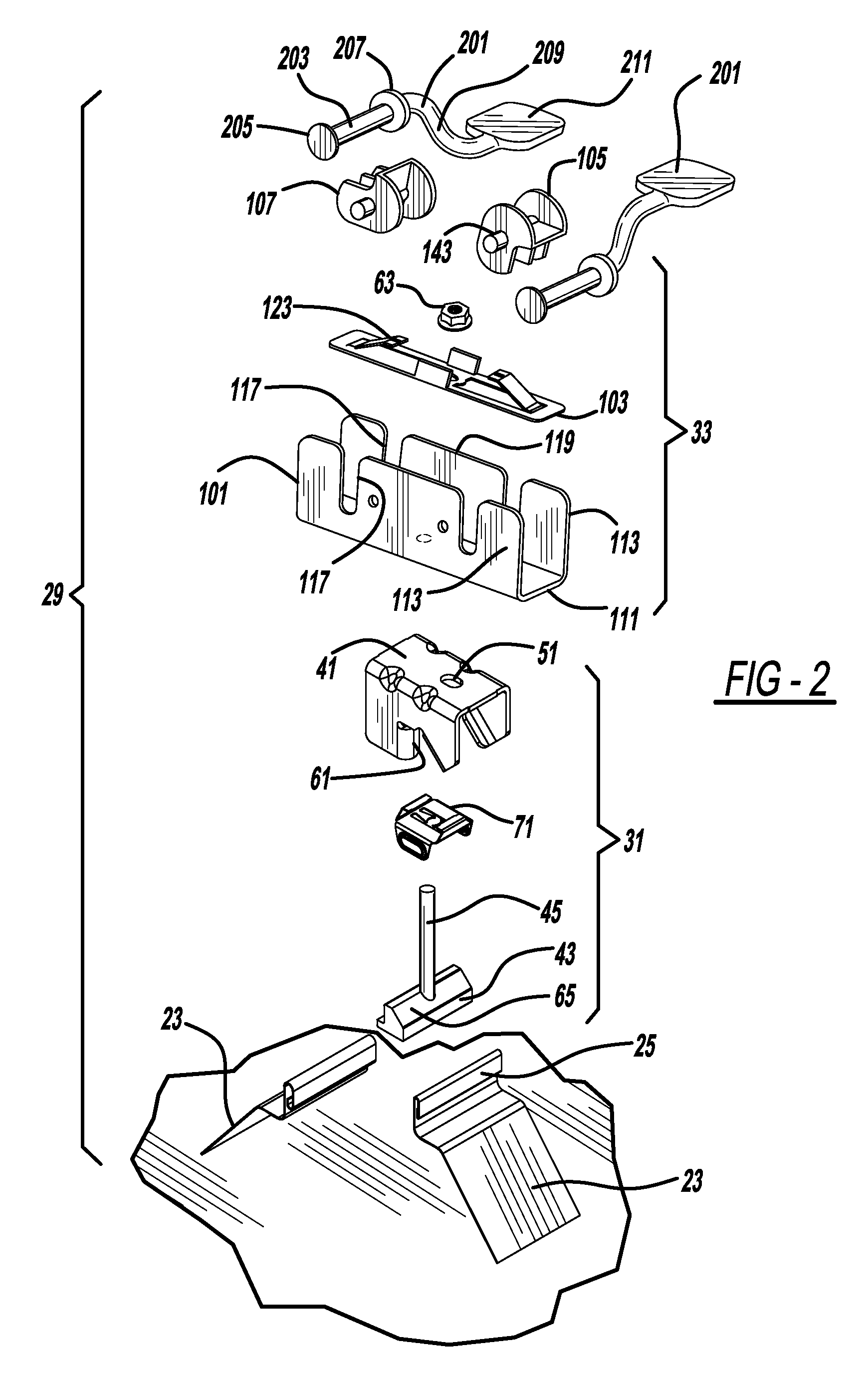
[0016]FIG. 1 illustrates a building 21 having a tilted roof 23, preferably made from sheet metal sections joined together at folded over, raised standing seams 25. Auxiliary roof components, preferably multiple solar panel assemblies 27, are secured to seams 25 by way of multiple attachment systems 29. Each attachment system 29 includes a roof clamp 31 and a latch assembly 33.

[0017]FIGS. 2 and 3 depict roof clamp 31 attached to seam 25 of roof 23. Roof clamp 31 includes a saddle 41, a roof seam-engaging wedge 43, and an elongated shaft or securing member 45. An optional part includes a retaining element 71. Securing member 45 fits into and aligns saddle 41 with wedge 43 so that upon engaging securing member 45, camming action of roof seam-engaging wedge 43 along saddle 41 secures roof clamp 31 to roof 23. Notably the same securing member 45 that secures roof clamp 31 to roof 23 also secures an auxiliary-retaining device, such as latch assembly 33, to roof 23 along a top surface of s...


PUM


Abstract

An attachment system is provided. In another aspect, a latching assembly is mounted to a building roof. Another aspect employs a moveable latch that removeably attaches an auxiliary component, such as a solar panel, to a building in a single motion and / or snap-in installation manner.

Description

CROSS-REFERENCE TO RELATED APPLICATIONS[0001]This application is a 371 National Phase of PCT / US2012 / 041525, filed Jun. 8, 2012, and published in English as WO 2012 / 170799 A2 on Dec. 13, 2012, which claims the benefit of U.S. Provisional Application Ser. No. 61 / 495,071, filed on Jun. 9, 2011, both of which are incorporated by reference herein.BACKGROUND AND SUMMARY[0002]The present application relates generally to an attachment system and more particularly to a solar panel attachment system for a roof of a building.[0003]Conventional photovoltaic or solar panels are mounted to roofs of buildings through screw-in clips or the like. Examples of such conventional devices are disclosed in U.S. Patent Publication No. 2011 / 0088740 entitled “Photovoltaic Panel Clamp” which published to Mittan et al. on Apr. 21, 2011, and U.S. Pat. No. 6,672,018 entitled “Solar Module Mounting Method and Clip” which issued to Shingleton on Jan. 6, 2004, both of which are incorporated by reference herein. Suc...

Claims


Application Information

Patent Timeline
Patent Type & Authority Patents(United States)
IPC IPC(8): E04D13/00F24J2/46F24J2/52H01L31/042H01L31/048
CPCF24J2/5245F24J2/5256F24J2/5249H01L31/0422H01L31/0482F24J2002/4665Y02B10/20Y02B10/12Y02E10/47Y02E10/50H02S20/23H02S20/00F24S25/615F24S25/634F24S2025/6004Y02B10/10F24S25/61
Inventor HEMINGWAY, TODD L.
Owner A RAYMOND & CO
Why Eureka
Try Eureka