Portable tower with improved guiding and lifting systems

a technology of applied in the direction of towers, building parts, building types, etc., can solve the problems of overcoming existing communication resources, unable to provide adequate communication resources for mobile devices, and becoming particularly problematic, so as to achieve the effect of improving guiding and lifting systems

a technology of applied in the direction of towers, building parts, building types, etc., can solve the problems of overcoming existing communication resources, unable to provide adequate communication resources for mobile devices, and becoming particularly problematic, so as to achieve the effect of improving guiding and lifting systems

US8955264B2Inactive Publication Date: 2015-02-17SOLARIS TECH

Image

  • Portable tower with improved guiding and lifting systems
  • Portable tower with improved guiding and lifting systems
  • Portable tower with improved guiding and lifting systems

Examples


Embodiment Construction

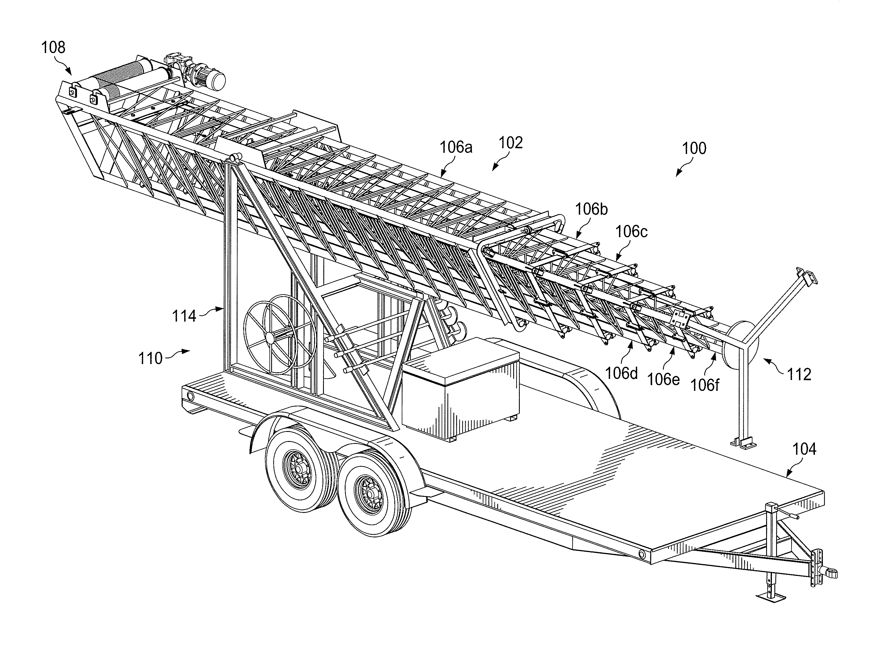
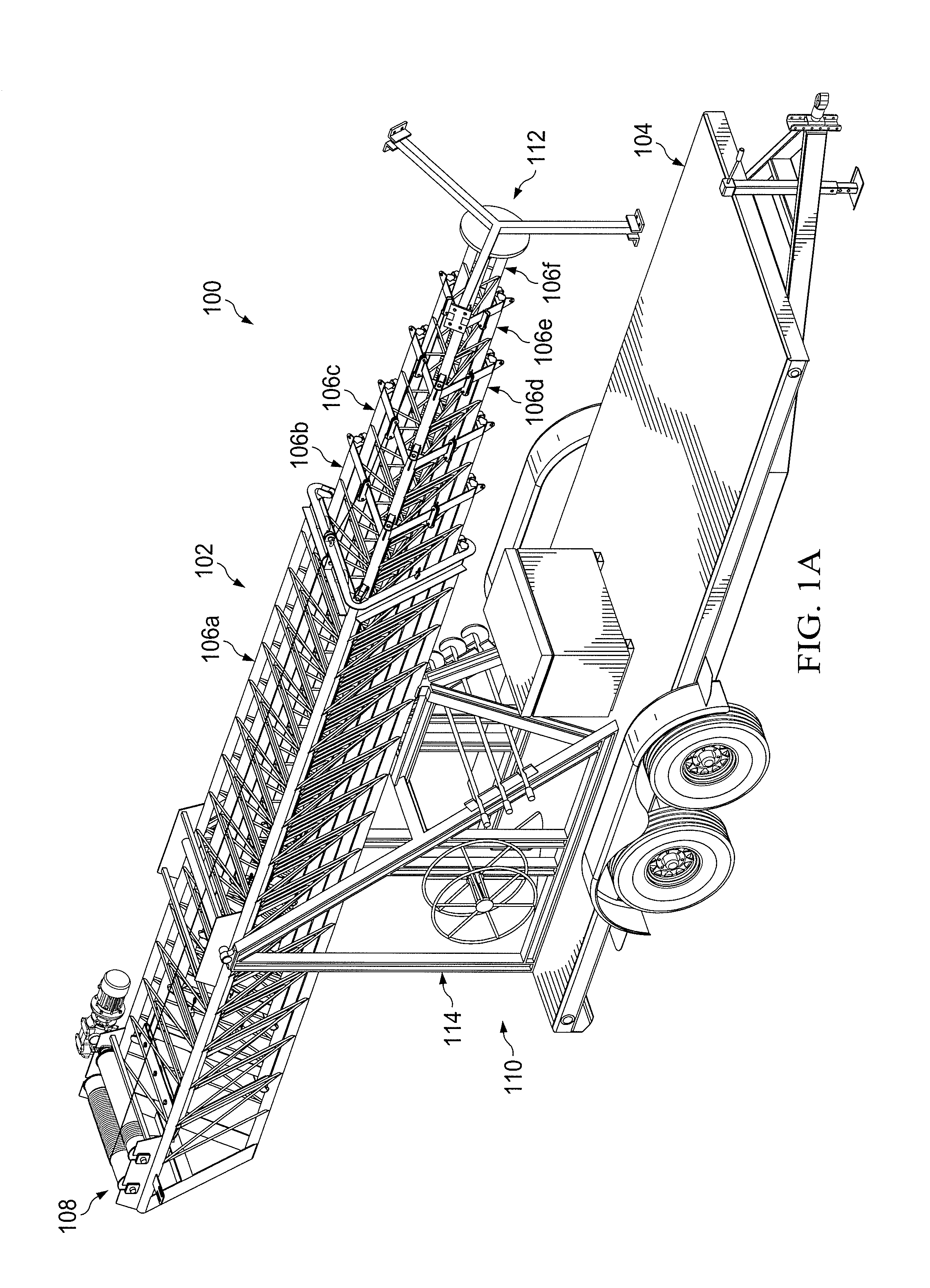
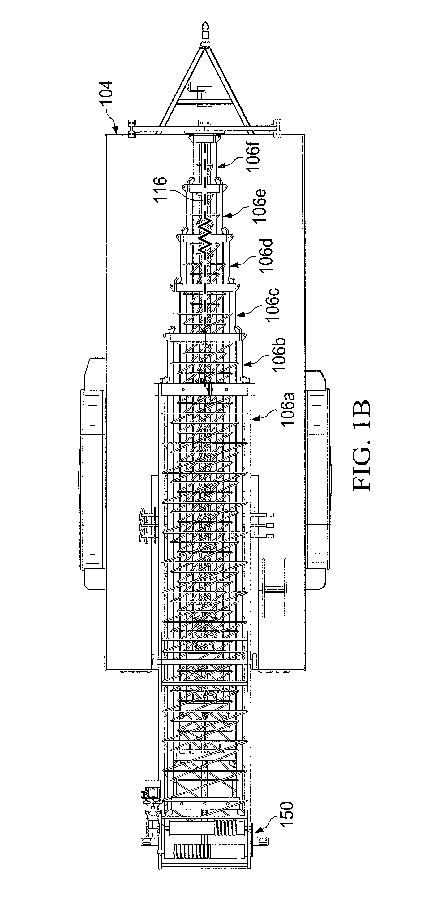
[0013]FIGS. 1A through 14, discussed below, and the various embodiments used to describe the principles of the present invention in this patent document are by way of illustration only and should not be construed in any way to limit the scope of the invention. Those skilled in the art will understand that the principles of the invention may be implemented in any type of suitably arranged device or system.

[0014]FIGS. 1A through 1C illustrate an example portable tower system 100 according to this disclosure. As shown in FIGS. 1A through 1C, the system 100 includes a tower 102 mounted on a trailer 104. The tower 102 generally represents a portable telescopic structure that can be raised or extended and lowered or retracted. The trailer 104 generally represents a portable base on which the tower 102 can be carried.

[0015]As shown in this example, the tower 102 represents a telescopic structure formed using multiple sections 106a-106f. These tower sections 106a-106f form a nested structur...


PUM


Abstract

An apparatus includes a portable tower having multiple sections including a base section and at least two slidable sections. The sections form a nested telescopic structure where each of the slidable sections is configured to move within another of the sections. The tower can also include a lifting system configured to extend the at least two slidable sections substantially simultaneously. Each section of the tower may also include multiple rollers configured to roll against at least one adjacent section of the tower.

Description

CROSS-REFERENCE TO RELATED APPLICATION AND PRIORITY CLAIM[0001]This application claims priority under 35 U.S.C. §119(e) to U.S. Provisional Patent Application No. 61 / 815,611, which is hereby incorporated by reference in its entirety.TECHNICAL FIELD[0002]This disclosure relates generally to portable telescopic towers. More specifically, this disclosure relates to a portable tower with improved guiding and lifting systems.BACKGROUND[0003]Various types of towers are routinely used in numerous types of environments. For example, mobile devices typically receive wireless services from one or more nearby communication towers. However, there are times when a given area lacks adequate communication resources for mobile devices. For instance, a large number of mobile devices may be present in a given area on a temporary basis. Specific examples of this can include large gatherings of people, such as in sporting and entertainment venues or during disaster recovery efforts. The presence of suc...

Claims


Application Information

Patent Timeline
17 Feb 2015
Publication
US8955264B2
IPC
E04H12/34; E04H12/18
CPC
E04H12/182; E04H12/34
Inventors
EDWARDS, JONATHAN; VILLASENOR, JOSE MANUEL