
Molded fiber optic cable furcation assemblies, and related fiber optic components, assemblies, and methods

a fiber optic cable and assembly technology, applied in the direction of fibre mechanical structures, instruments, applications, etc., can solve the problems of fiber optic communication networks that can present certain challenges, optical networks that are more difficult to install, and fiber optic networks that are difficult to install

Active Publication Date: 2015-02-17
CORNING OPTICAL COMM LLC
View PDF60 Cites 12 Cited by
  • Summary
  • Abstract
  • Description
  • Claims
  • Application Information

AI Technical Summary

Benefits of technology

This patent describes a way to create a molded fiber optic cable furcation plug that can be used to pull cables without damaging the optical fibers inside them. This method is advantageous because it requires fewer parts, doesn't require epoxy, and is easy to automate.

Problems solved by technology

However, the installation of optical networks can be more challenging to install and as a result “plug and play” components and systems are generally preferred by the craft.
Use of preconnectorized distribution cables in a fiber optic communications network can present certain challenges.
Transferring a tensile load to optical fibers disposed in a fiber optic cable during the pulling (i.e., installation) of a fiber optic cable could damage the optical fibers.
There are challenges when forming a conventional furcation plug on a fiber optic cable to provide a fiber optic cable furcation assembly.
For instance, use of epoxy as a bonding and structural agent to secure optical fibers and / or strength members of the fiber optic cable is labor intensive and can suffer from defects related to epoxy voids created within a furcation plug.
Further, manufacturing methods using epoxy within the furcation plug may not easily be automated.
Heat shrink or other components that may damage the cable jacket may be required to maintain the epoxy within the furcation plug during assembly.
Therefore, there is an unresolved need for fiber optic cable furcation assemblies that solve the problems associated with the prior art furcation assemblies such as manufacturing complexity, cost, defects and the like.

Method used


Image

  • Molded fiber optic cable furcation assemblies, and related fiber optic components, assemblies, and methods
  • Molded fiber optic cable furcation assemblies, and related fiber optic components, assemblies, and methods
  • Molded fiber optic cable furcation assemblies, and related fiber optic components, assemblies, and methods

Examples


Embodiment Construction

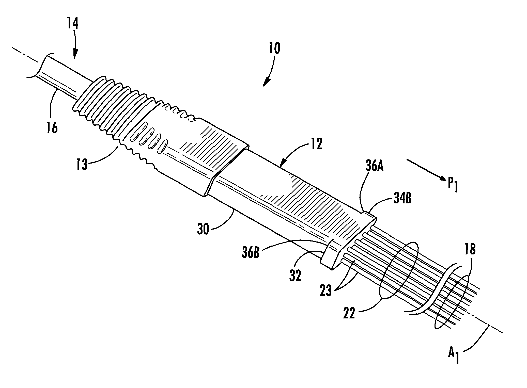
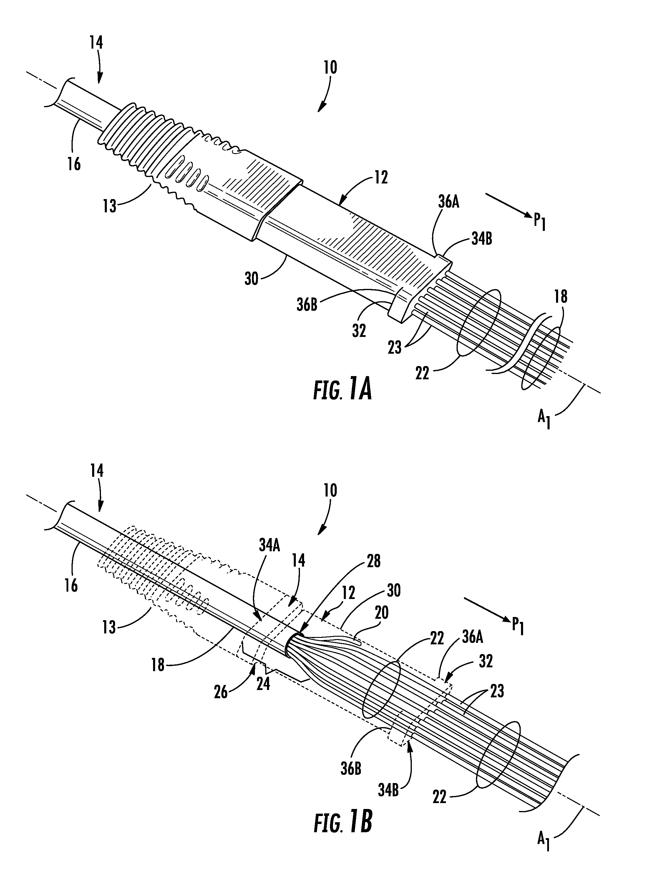
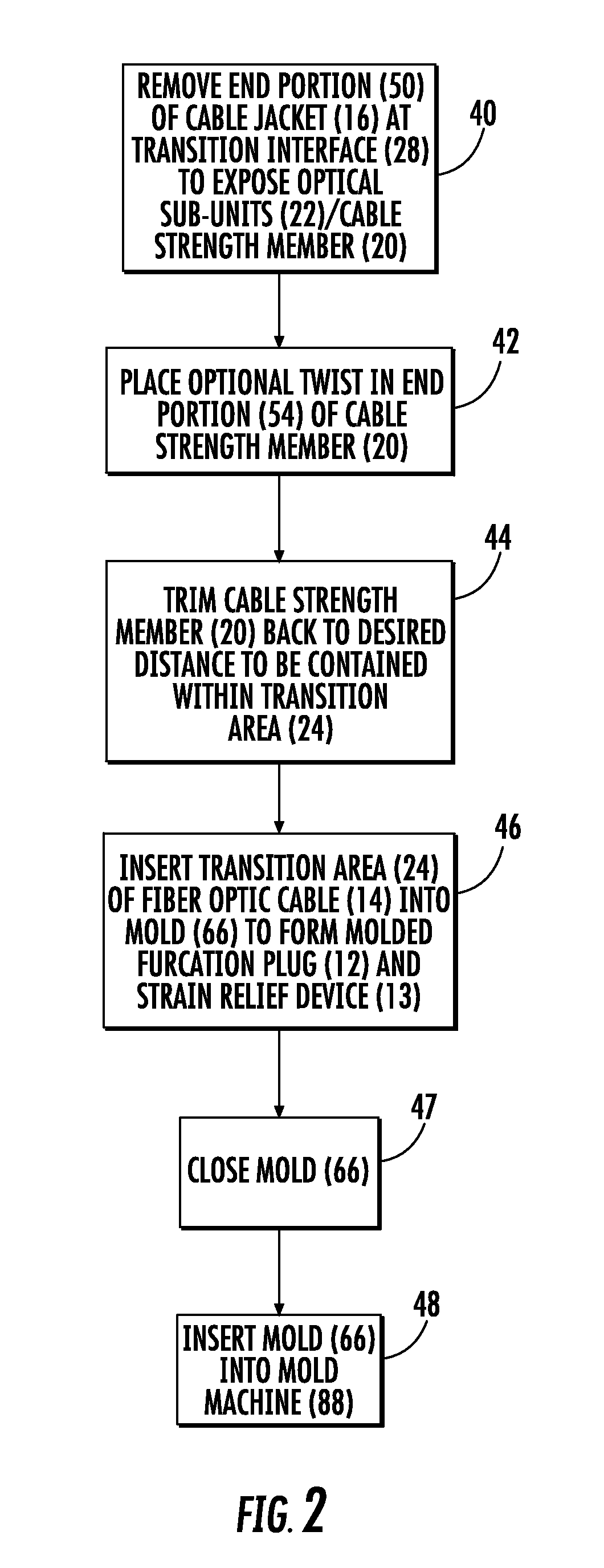
[0010]Embodiments disclosed in the detailed description include molded fiber optic cable furcation assemblies, and related fiber optic components, assemblies, and methods. In one embodiment, an end portion of a fiber optic cable with a portion of a cable jacket removed to expose optical fibers and / or a strength member(s) therein can be disposed in a mold to create a molded furcation plug about the end portion of the fiber optic cable. The molded furcation plug may be overmolded about the end portion of the fiber optic cable. The molded furcation plug can be used to pull a fiber optic cable without damaging the optical fiber(s) disposed within the fiber optic cable. The molded furcation plug is advantageous since it may be manufactured with fewer parts, without epoxy, and / or without a labor intensive process that may be difficult to automate.

[0011]In this regard in one embodiment, a method of preparing a fiber optic cable furcation assembly is provided. This method includes providing...


PUM


Abstract

Molded fiber optic cable furcation assemblies, and related fiber optic components, assemblies, and methods are disclosed. In one embodiment, an end portion of a fiber optic cable with a portion of a cable jacket removed to expose optical fibers and / or a cable strength member(s) therein and thereafter placing the cable into a mold for creating a molded furcation plug about the end portion of the fiber optic cable. The furcation plug may be overmolded about the end portion of the fiber optic cable. The molded furcation plug can be used to pull a fiber optic cable without damaging the optical fiber(s) disposed within the fiber optic cable. The molded furcation plug is advantageous since it manufactured with fewer parts, without epoxy, and / or without a labor intensive process that may be difficult to automate.

Description

RELATED APPLICATION[0001]This application claims the benefit of priority under 35 U.S.C. §119 of U.S. Provisional Application No. 61 / 490,771 filed on May 27, 2011, the content of which is relied upon and incorporated herein by reference in its entirety.BACKGROUND[0002]1. Field of the Disclosure[0003]The technology of the disclosure relates to fiber optic cable furcation assemblies for fiber optic cables, which may be used in establishing interconnection points in fiber optic communications networks.[0004]2. Technical Background[0005]Benefits of optical fiber use include extremely wide bandwidth and low noise operation. Because of these advantages, optical fiber is increasingly being used for a variety of applications, including but not limited to broadband voice, video, and data transmission. Consequently, optical fiber networks are displacing copper communication networks. However, the installation of optical networks can be more challenging to install and as a result “plug and pla...

Claims


Application Information

Patent Timeline
Patent Type & Authority Patents(United States)
IPC IPC(8): G02B6/44G02B6/38
CPCG02B6/4471G02B6/3889G02B6/4477G02B6/44785
Inventor CLINE, TIMOTHY S.COOKE, TERRY L.KLAVUHN, TORY A.TOOLEY, MARIO L.
Owner CORNING OPTICAL COMM LLC
Learn More