Dual band WLAN MIMO high isolation antenna structure

a high isolation, antenna technology, applied in the field of antennas, can solve the problem that the substantially two-dimensional space of the substrate cannot be implemented

Active Publication Date: 2015-02-17
AVAGO TECH INT SALES PTE LTD
View PDF16 Cites 5 Cited by
  • Summary
  • Abstract
  • Description
  • Claims
  • Application Information

AI Technical Summary

Problems solved by technology

An issue with such three-dimensional antennas is that they cannot be implemented in the substantially two-dimensional space of a substrate such as an integrated circuit (IC) and / or on the printed circuit board (PCB) supporting the IC.

Method used


Image

  • Dual band WLAN MIMO high isolation antenna structure
  • Dual band WLAN MIMO high isolation antenna structure
  • Dual band WLAN MIMO high isolation antenna structure

Examples


Embodiment Construction

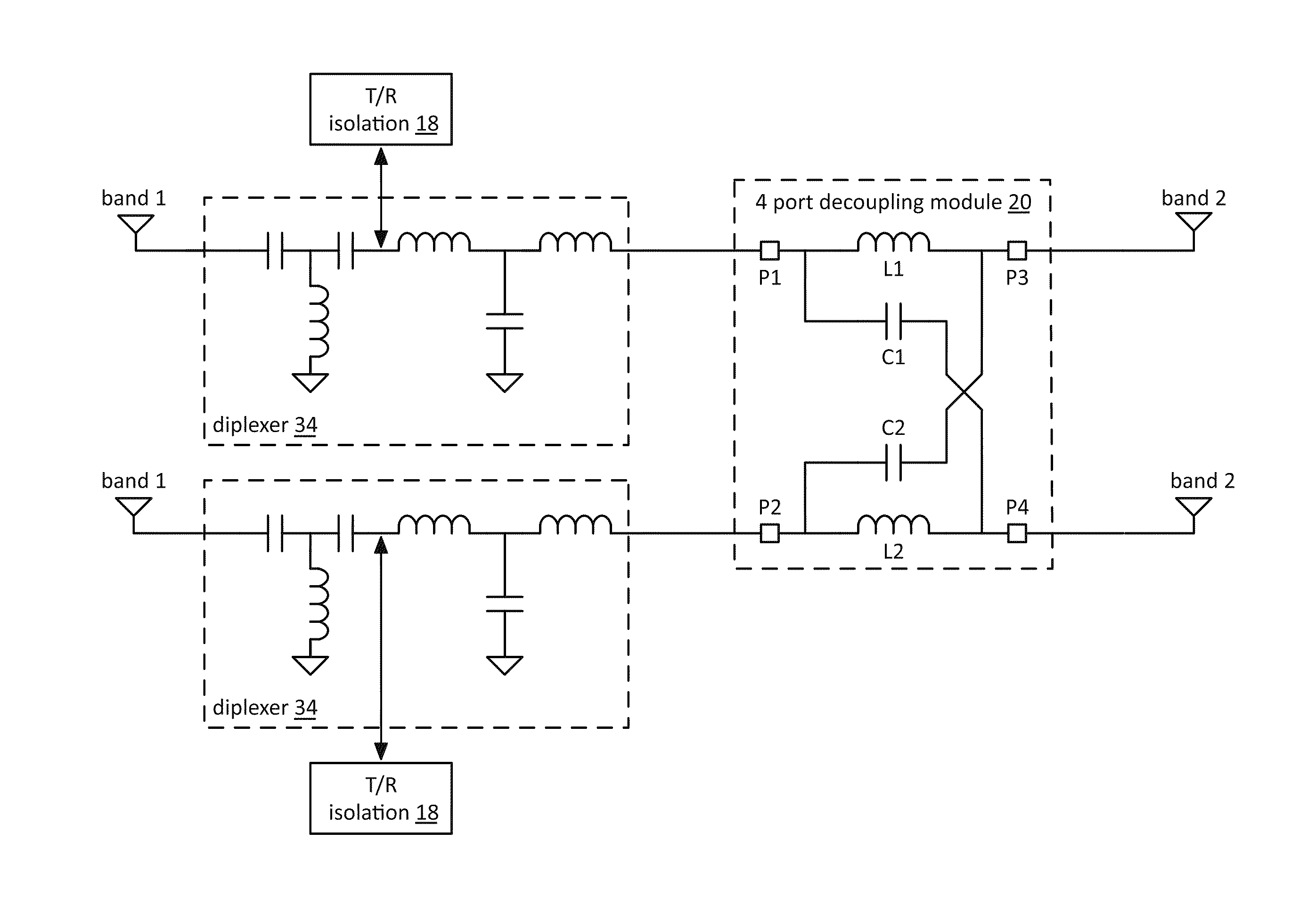
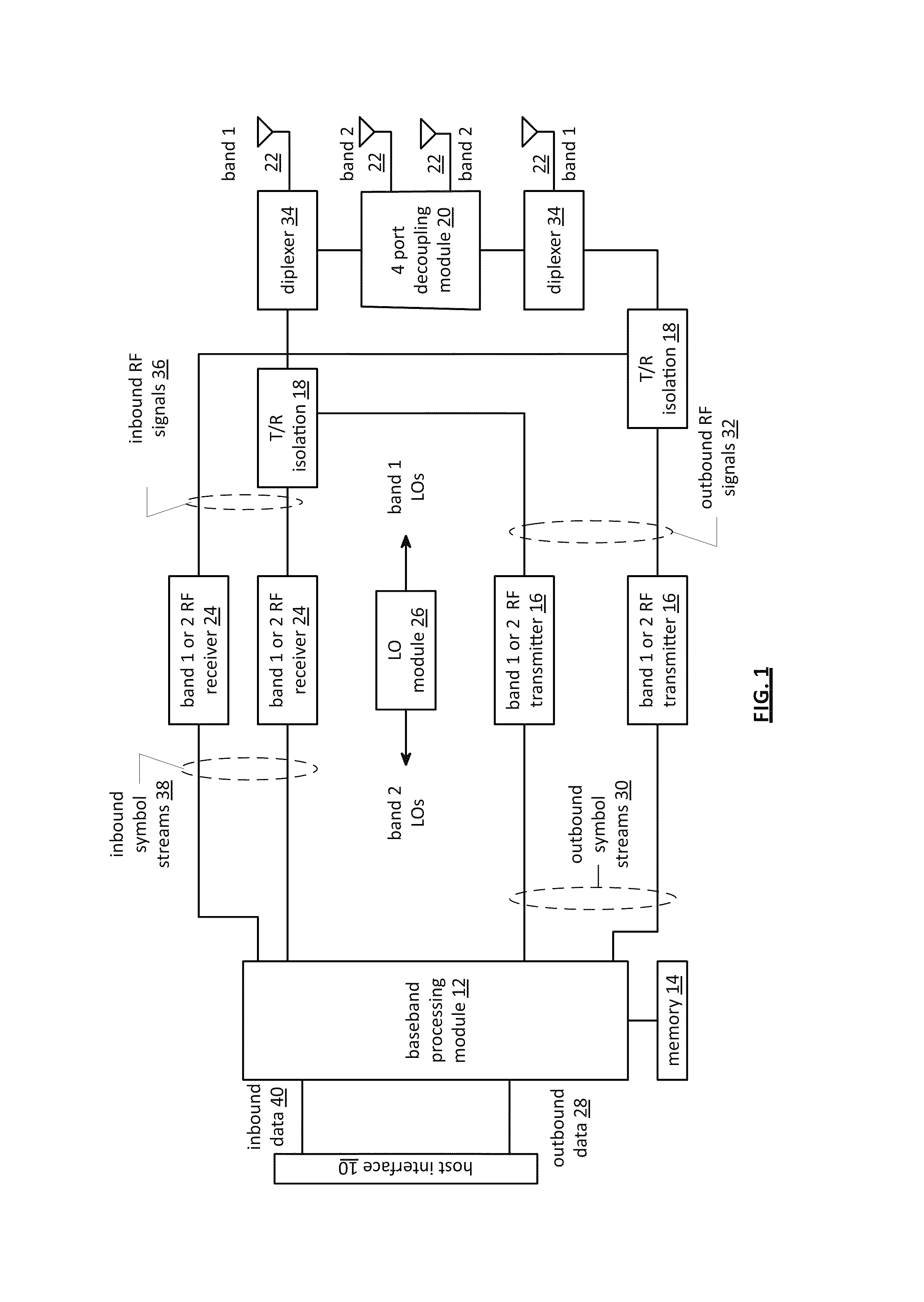
[0025]FIG. 1 is a diagram of a transceiver that includes a host interface 10, a baseband processing module 12, memory 14, a local oscillation (LO) module 26, a plurality of multiple band radio frequency (RF) transmitters 16, transmit / receive (T / R) isolation modules 18, a four port decoupling module 20, a plurality of antennas 22, a plurality of multiple band RF receivers 24, and a local oscillation module 26. In an embodiment, a radio module includes a receiver section (e.g., the plurality of multiple band RF receivers 24), a transmitter section (e.g., the plurality of multiple band RF transmitters 16), and a dual band high isolation antenna structure. The dual band high isolation antenna structure includes a diplexer unit (e.g., the diplexers 34), the 4-port decoupling module 20, a first frequency band antenna assembly (e.g., antennas 22 of band 1), and a second frequency band antenna assembly (e.g., antennas 22 of band 2).

[0026]The baseband processing module 12, in combination wit...


PUM


Abstract

A dual band high isolation antenna structure includes a diplexer unit, a 4-port decoupling module, a first frequency band antenna assembly, and a second frequency band antenna assembly. The diplexer unit is operable to frequency domain multiplex between a first frequency band and a second frequency band. The 4-port decoupling module is operably coupled to the diplexer unit and is operable to isolate a first pair of ports from a second pair of ports. The first frequency band antenna assembly is operably coupled to the diplexer unit and is operable to transceive wireless signals in the first frequency band. The second frequency band antenna assembly is operably coupled to a port in each of the first and second pairs of ports and is operable to transceive wireless signals in the second frequency band.

Description

CROSS REFERENCE TO RELATED PATENTS[0001]This patent application is claiming priority under 35 USC §119(e) to a provisionally filed patent application entitled, “Dual Band WLAN MIMO High Isolation Antenna Structure”, having a provisional filing date of Mar. 22, 2010, and a provisional Ser. No. 61 / 316,094, and is also claiming priority under 35 USC §120 as a continuation-in-part patent application of co-pending patent application entitled, “Dongle Transceiver and Antenna Assembly”, having a filing date of Jan. 6, 2011, and a Ser. No. 12 / 985,527, all of which are hereby incorporated herein by reference in its entirety and made part of the present U.S. Utility Patent Application for all purposes.STATEMENT REGARDING FEDERALLY SPONSORED RESEARCH OR DEVELOPMENT[0002]Not ApplicableINCORPORATION-BY-REFERENCE OF MATERIAL SUBMITTED ON A COMPACT DISC[0003]Not ApplicableBACKGROUND OF THE INVENTION[0004]1. Technical Field of the Invention[0005]This invention relates generally to wireless communic...

Claims


Application Information

Patent Timeline
Patent Type & Authority Patents(United States)
IPC IPC(8): H04M1/00H01Q1/22H01Q1/52H01Q5/00H01Q5/10H01Q21/28H01Q21/30H04B1/00H04B7/06H04B7/10H04L5/00
CPCH04B1/405H01Q1/521H01Q1/22H01Q5/0093H01Q21/28H01Q21/30H04B1/0064H04B7/0669H04B7/068H04B7/10H04L5/0023H01Q5/50
Inventor ALEXOPOULOS, NICOLAOS G.YOON, SEUNGHWAN
Owner AVAGO TECH INT SALES PTE LTD
Why Eureka
Try Eureka