
Micro-extrusion printhead with nozzle valves

a technology of nozzle valves and printheads, which is applied in the direction of turning machine accessories, drawing profiling tools, liquid transfer devices, etc., to achieve the effect of convenient parallel or sequential control, convenient gridline printing, and convenient controllable ink flow

Active Publication Date: 2015-02-24
XEROX CORP
View PDF232 Cites 0 Cited by
  • Summary
  • Abstract
  • Description
  • Claims
  • Application Information

AI Technical Summary

Benefits of technology

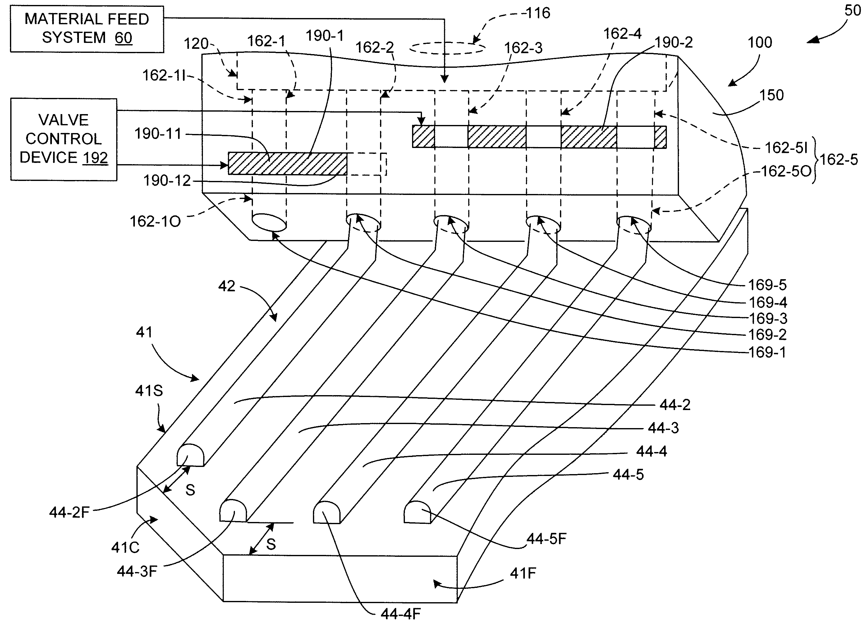
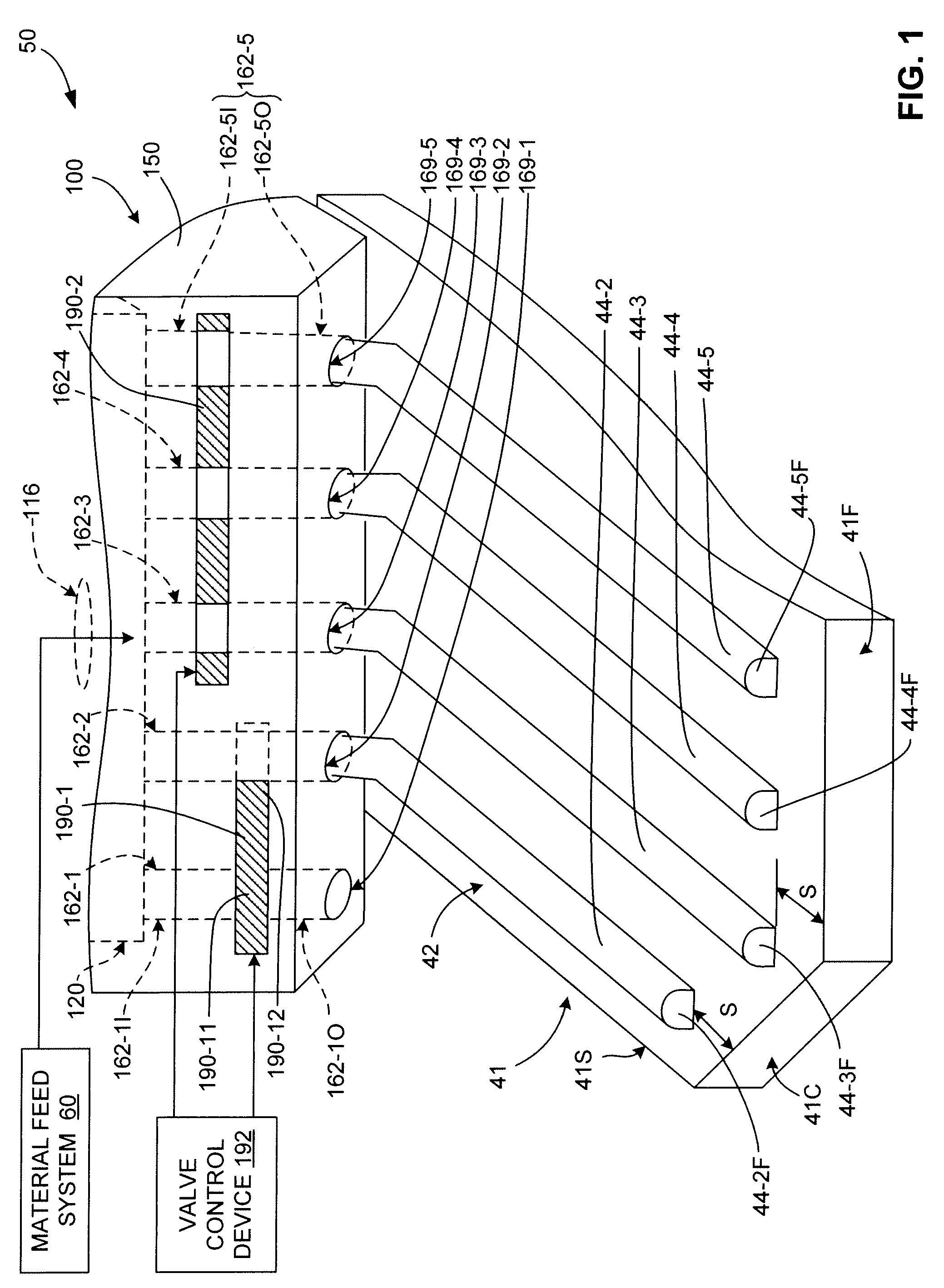
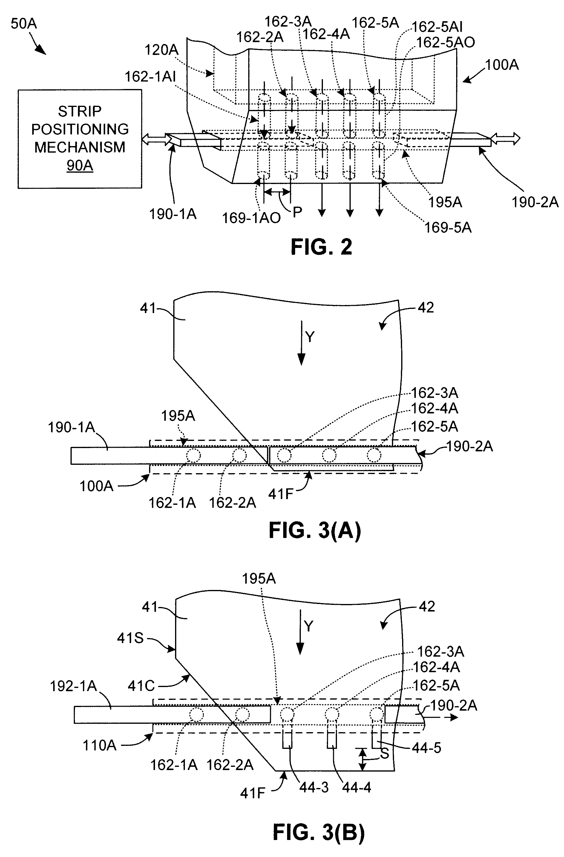
The present invention is a system for printing solar cells using a long printhead with valve structures to control the flow of ink. The valve structures are located within the printhead and can be adjusted to control the ink flow from selected nozzle channels onto the solar panel substrate during the printing process. This allows for parallel or sequential control of ink flow, and also provides a mechanism for automatically correcting misalignment of the solar panel substrate in the cross-process direction. By providing the valve structures inside the printhead and adjacent to the nozzle outlet orifices, the present invention reduces the occurrence of segmented gridlines associated with conventional printheads and shortens the distance between a high pressure material source and the solar panel substrate at the start and end of each gridline printing process.

Problems solved by technology

The valving is not used to control the flow of a non-conductive ink, which is allowed to pass through the printhead assembly and onto the solar panel substrate, because the non-conductive ink does not produce electrical shorts.

Method used


Image

  • Micro-extrusion printhead with nozzle valves
  • Micro-extrusion printhead with nozzle valves
  • Micro-extrusion printhead with nozzle valves

Examples


Embodiment Construction

[0027]The present invention relates to an improvement in micro-extrusion systems, and more particularly to micro-extrusion systems used in the production of solar cells. The following description is presented to enable one of ordinary skill in the art to make and use the invention as provided in the context of a particular application and its requirements. As used herein, directional terms such as “upper”, “top”, “lower”, “bottom”, “front”, “rear”, and “lateral” are intended to provide relative positions for purposes of description, and are not intended to designate an absolute frame of reference. Various modifications to the preferred embodiment will be apparent to those with skill in the art, and the general principles defined herein may be applied to applications other than the production of solar cells. Therefore, the present invention is not intended to be limited to the particular embodiments shown and described, but is to be accorded the widest scope consistent with the princ...


PUM

PropertyMeasurementUnit
pressureaaaaaaaaaa
conductiveaaaaaaaaaa
non-conductiveaaaaaaaaaa

Abstract

A solar cell extrusion printing system includes a printhead assembly having one or more elongated valve structures that are adjustably disposed adjacent to the outlet orifices of selected nozzle channels, and a valve control device for controlling the position of the valve structures to facilitate controllable ink flow through selected nozzle channels of the printhead assembly during the gridline printing process. The printhead assembly defines an elongated opening (e.g., a slot or hole) that that intersects (i.e., passes through) each of the selected nozzle channels, and an elongated member is movably disposed in the slot and is selectively movable between a first (opened) position, in which the valve structure extrusion material is passed by the valve structure through the nozzle channel and out of the printhead, and a closed position, in which the extrusion material is blocked by the valve structure and prevented from passing through the nozzle channel.

Description

FIELD OF THE INVENTION[0001]The present invention is related to the production of wafer-based electronic devices, and more particularly to the production of frontside metallization on H-pattern solar cells using micro-extrusion techniques.BACKGROUND[0002]FIG. 7 is a simplified diagram showing an exemplary conventional H-pattern contact solar cell 40 that converts sunlight into electricity by the inner photoelectric effect. Solar cell 40 is formed on a semiconductor (e.g., monocrystalline silicon) substrate 41 that is processed using known techniques to include an n-type doped upper region 41A and a p-type doped lower region 41B such that a pn-junction is formed near the center of substrate 41. Disposed on a frontside surface 42 of semiconductor substrate 41 are a series of parallel metal gridlines (fingers) 44 (shown in end view) that are electrically connected to n-type region 41A. A substantially solid conductive layer 46 is formed on a backside surface 43 of substrate 41, and is ...

Claims


Application Information

Patent Timeline
Patent Type & Authority Patents(United States)
IPC IPC(8): B05D5/12B67D3/00B41J2/005H01L31/0224
CPCB41J2/005H01L31/022425Y02E10/50B05D1/265B41J2/1645H01L21/6715H01L31/18H01L31/1888H01M14/005
Inventor ELDERSHAW, CRAIGDUFF, DAVID G.
Owner XEROX CORP
Learn More