Articulated conduit systems and uses thereof for fuel gas transfer between a tug and barge

Active Publication Date: 2015-03-03
MORAN TOWING
View PDF55 Cites 13 Cited by
  • Summary
  • Abstract
  • Description
  • Claims
  • Application Information

AI Technical Summary

Benefits of technology

[0006]Aspects of the disclosure are based on a recognition that current systems for transporting fuel gas between a tug to barge are limited by the fact that they fail to adequately account for differential movement between the tug and barge. The inventors have found that the gas transfer assembly in Van Tassel fails to adequately account for differential movement between the tug and barge. In particular, the gas transfer assembly in Van Tassel (as depicted in FIGS. 10 and 11 therein) does not contain the requisite degrees of freedom to allow for normal operation when installed on an articulated tug and barge. In particular, the Van Tassel gas transfer assembly does not allow for the variations in draft, relative diff

Problems solved by technology

Aspects of the disclosure are based on a recognition that current systems for transporting fuel gas between a tug to barge are limited by the fact that they fail to adequately account for differential movement between the tug and barge.
The inventors have found that the gas transfer assembly in Van Tassel fails to adequately account for differential movement between the tug and barge.
In particular, the gas transfer assembly in Van Tassel (as depicted in FIGS. 10 and 11 therein) does not contain the requisite degrees of freedom to allow for normal operation when installed on an articulated tug and barge.
In particular, the Van Tassel gas transfer assembly does not allow for the variations in draft, relative difference in heel angle between two vessels (e.g., rotation of a tug about its longitudinal axis relative to a barge), and variations in alignment relative to the pin c

Method used


Image

  • Articulated conduit systems and uses thereof for fuel gas transfer between a tug and barge
  • Articulated conduit systems and uses thereof for fuel gas transfer between a tug and barge
  • Articulated conduit systems and uses thereof for fuel gas transfer between a tug and barge

Examples


example 1

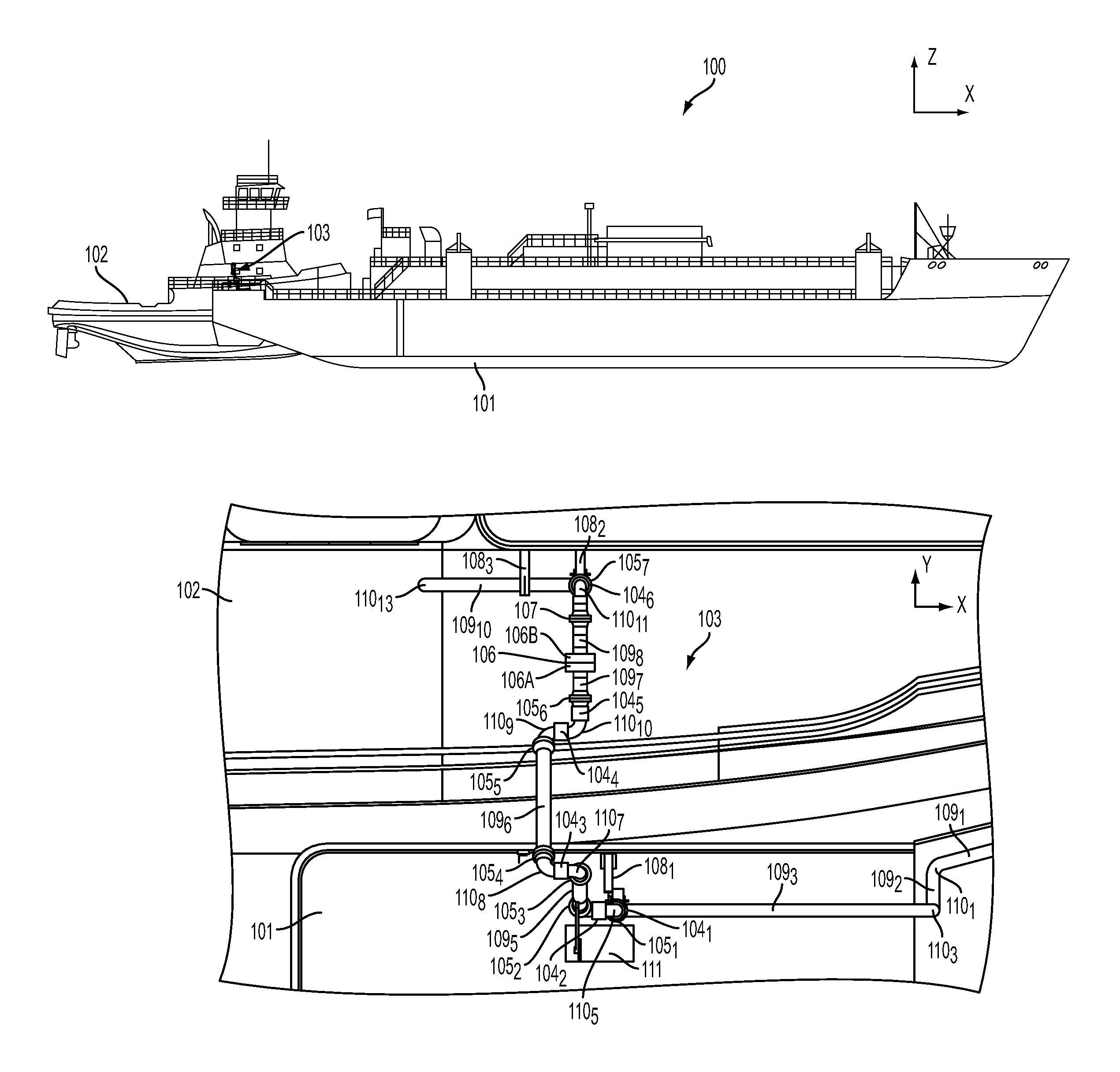
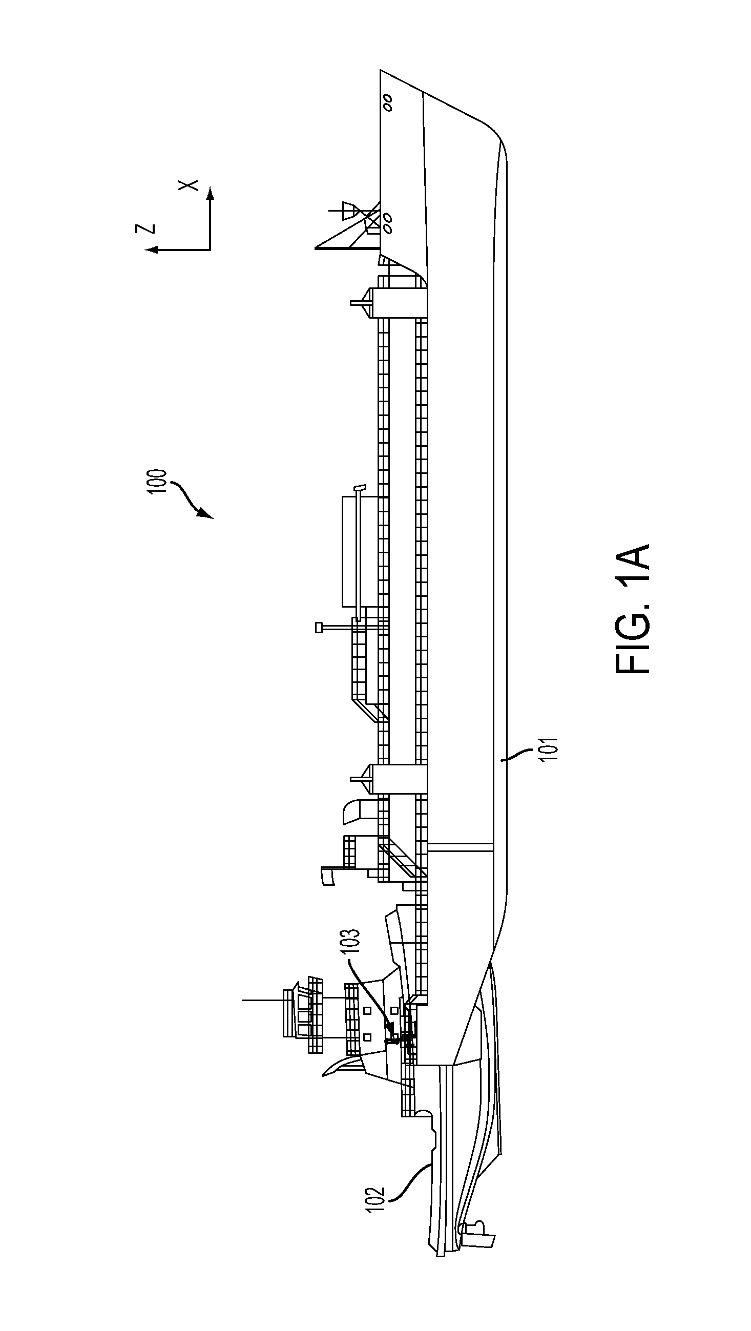
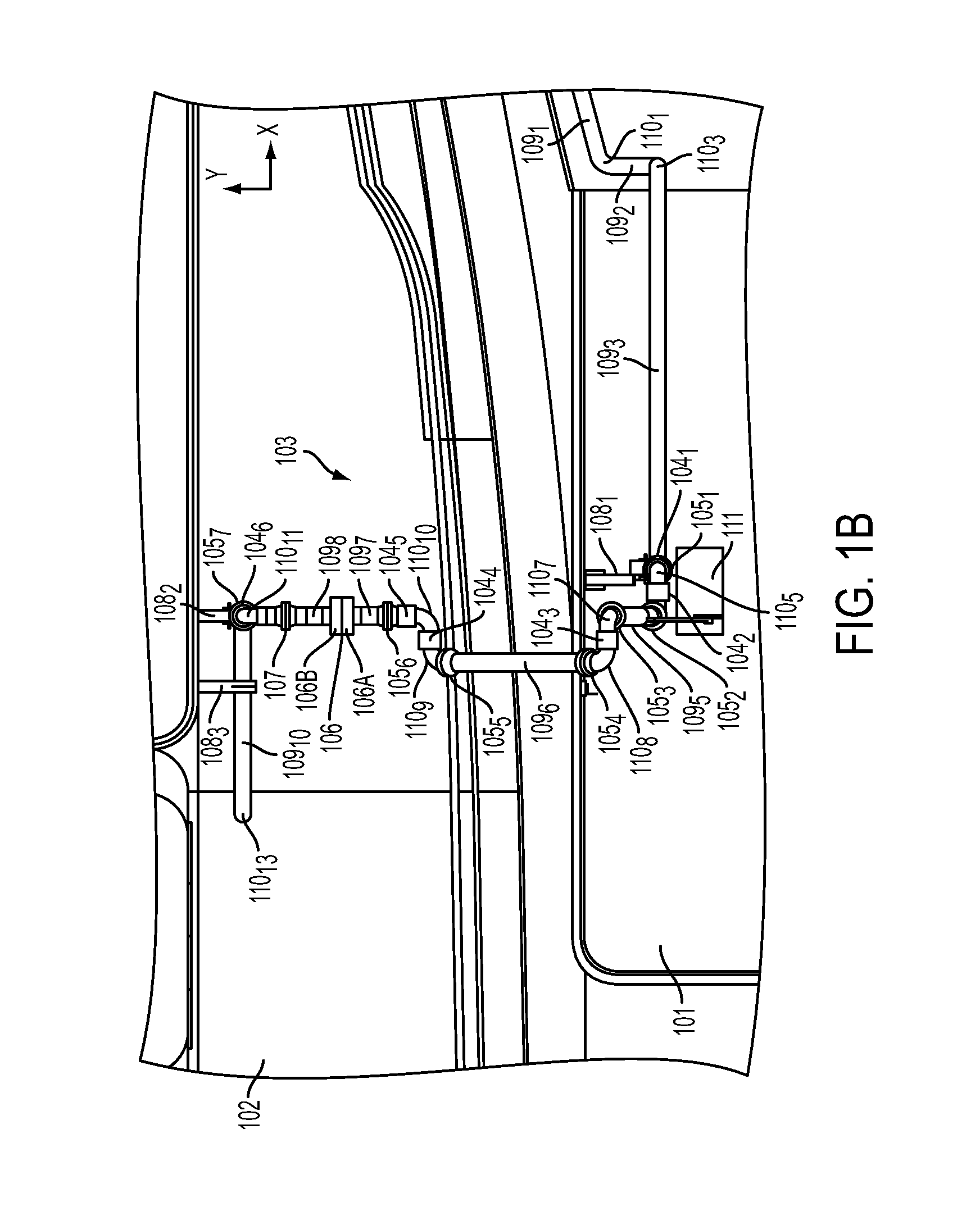
Articulated Conduit System on a Liquefied Natural Gas (LNG) Articulated Tug Barge (ATB)

[0101]The tug is a dual fuel vessel that is intended to utilize gaseous natural gas as a fuel gas to supply the main propulsion generator engines while coupled to the barge. The fuel gas is supplied to the tug from the barge via an articulated conduit system capable of handling the relative motions between the tug and barge.

[0102]

Tug Characteristics:Length Overall100′-0″Breadth 38′-0″Depth at Side, Midship 18′-4″Design Draft to DWL 13′-6″Barge Characteristics:Length Overall241-8″Breadth 60′-0″Depth at Sides 23′-6″Full Load Draft (approx.) 15′-0″Ballasted Draft (approx.) 12′-0″

Natural Gas Supply Characteristics:

[0103]The natural gas is in a gaseous state as it flows from the barge to the tug. Natural Boil Off Gas (BOG) from the barge LNG storage tanks is consumed, with any additional fuel gas demand provided by two fuel gas vaporizers located on the barge. Note that, for this example, based on the ...

example 2

Operation Sequences for an Articulated Conduit System on a LNG ATB

[0123]An operation sequence is provided below for an articulated conduit system that is installed on a LNG ATB.

[0124]Coupling of the Articulated Conduit System and Establishing Fuel Gas Operation on Board the Tug Involves the Following:

[0125]1) The tug approaches the barge while the tug is operating on diesel fuel. The tug's main propulsion generators remain online as it approaches the barge.

[0126]2) The tug enters the notch at the stern of the barge. Once inside the notch, the Intercon pins extend from the tug and enter corresponding recesses provided within the stern notch of the barge. The crew confirms a positive link once the pins have entered the recesses.

[0127]3) The crew then starts the barge generators and brings barge power online. The fuel gas system onboard the barge is started for automatic operation, and operating pressure in a fuel gas buffer vessel is established and maintained. The fuel gas buffer ves...


PUM

PropertyMeasurementUnit
Angleaaaaaaaaaa
Degree of freedomaaaaaaaaaa

Abstract

According to some aspects, a tug and barge arrangement is provided that is configured with an articulated conduit system for transferring a fuel gas (e.g., natural gas) between the tug and barge. In some embodiments, an articulated conduit system is provided that comprises a plurality of conduits fluidically interconnected by rotatable joints configured to permit positional alterations of the fluid conduits that result from differential movement between a tug and barge, such as relative vertical displacement between the tug and barge and/or relative rotation between the tug and barge about a forward-aft axis of the tug.

Description

RELATED APPLICATIONS[0001]This application is a continuation application which claims the benefit under 35 U.S.C. §120 of U.S. application Ser. No. 14 / 242,701, entitled “ARTICULATED CONDUIT SYSTEMS AND USES THEREOF FOR FLUID TRANSFER BETWEEN TWO VESSELS” filed on Apr. 1, 2014, which is herein incorporated by reference in its entirety.BACKGROUND[0002]1. Field[0003]Aspects of the disclosure relate to systems and methods for transporting fluids between two vessels, such as a tug and barge.[0004]2. Discussion of Related Art[0005]Tug and barge vessel combinations can be configured to transport gaseous fuels stored as liquid on board the barge. Certain amounts of the stored liquid vaporize to gas, which can be managed in multiple ways. For example, the gas can be i) burned off, ii) re-liquefied and returned to the barge storage tanks, and / or iii) used as fuel for secondary systems on board the barge. In some configurations, vaporized gas can provide an auxiliary fuel source for the tug. T...

Claims


Application Information

Patent Timeline
IPC IPC(8): F17D1/08B63B21/56
CPCB63B21/56B63B2021/563B63B27/30Y10T137/8807Y10T137/0318Y10T137/6906B63B27/34
Inventor PERREAULT, SEAN REILEYLEFFERS, CURTISRODDY, MATTHEW WILLIAMWICHGERS, MATTHEW JACOBRICE, JEREMY PAUL
Owner MORAN TOWING
Why Eureka
Try Eureka