Bushing

a technology of bushings and shock absorbers, applied in the field of bushings, can solve the problems of increasing the load of suspensions that need to be withstood, introducing packaging problems in the design of suspensions, and affecting the performance of suspensions, so as to reduce the load of high shocks, prevent the increase of stiffness, and control the stiffness of the bushings

Inactive Publication Date: 2015-03-03
JAGUAR LAND ROVER LTD
View PDF11 Cites 9 Cited by
  • Summary
  • Abstract
  • Description
  • Claims
  • Application Information

AI Technical Summary

Benefits of technology

[0010]The bushing may be advantageously utilized as a suspension mount in a motor vehicle, for example, between a suspension component and the vehicle's chassis or body. The arrangement of these two resilient components in series permits high shock loads to be reduced through the outer linear component preventing the increase in stiffness which is inherent in the inner component.
[0011]At low loads, the inner component makes the greater contribution to absorbing the shock, thus controlling the stiffness of the bushing, whereas at high loads, the outer component dominates the compliance of the bushing.

Problems solved by technology

The current automotive trend for large wheels and low profile tires results in increasing suspension loads needing to be withstood by the suspension structure and bushings.
However, large rubber bushes have a tendency to induce steering wheel shimmy and large hydraulic bushes tend to degrade impact performance, making the suspension feel harsh.
A large bushing also introduces packaging problems in the design of the suspension.
The presence of the polyurethane material permits good isolation of low amplitude, high frequency vibrations but would be too weak to withstand high impact loads, such as a vehicle tire striking the edge of a pothole, for example.

Method used


Image

  • Bushing
  • Bushing
  • Bushing

Examples


Embodiment Construction

)

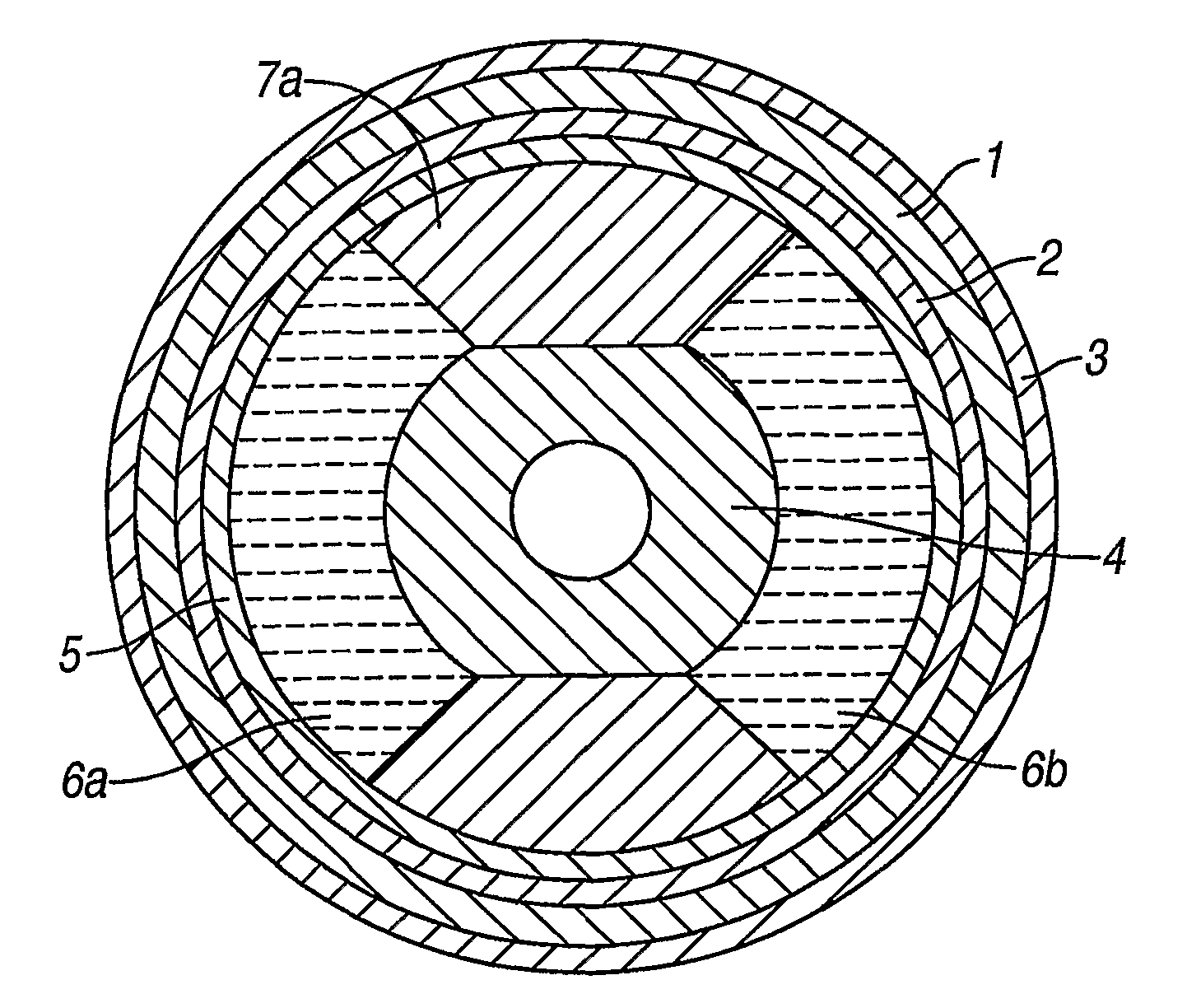
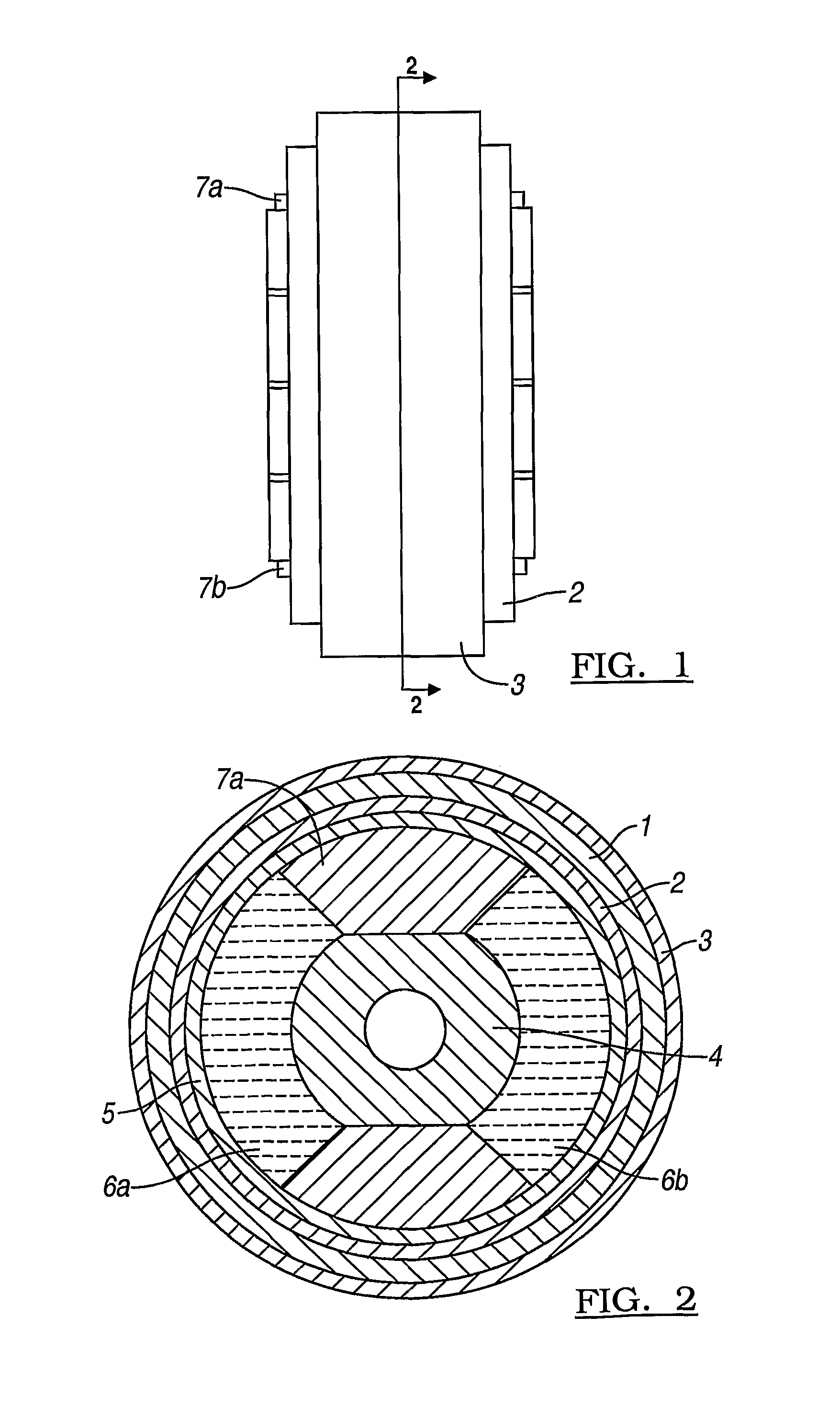
[0017]The bushing of FIGS. 1 and 2 comprises an inner hydraulic bushing in series with an outer rubber bushing.

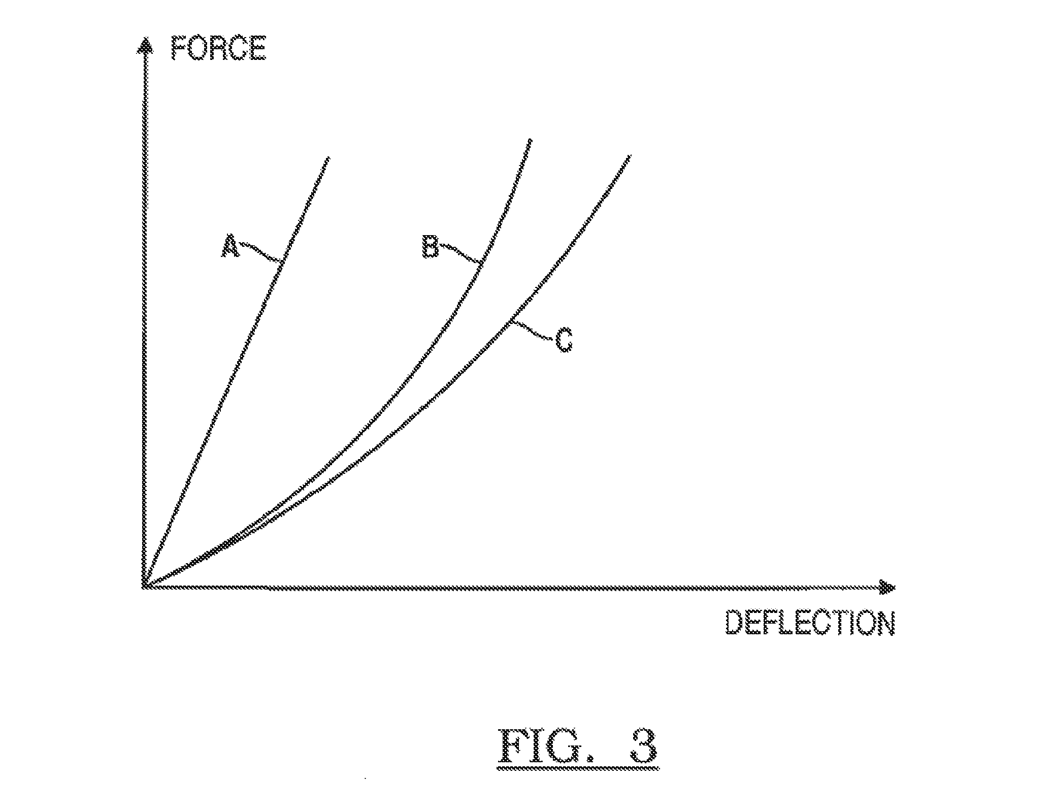
[0018]The outer rubber bushing comprises a cylindrical piece of rubber 1 supported around its inner and outer perimeters by metal cylinders 2 and 3 respectively. This outer rubber bushing has a stiffness characteristic as illustrated by curve A in FIG. 3 i.e. its deflection increases in a substantially linear fashion with increasing applied force.

[0019]The inner hydraulic bushing is supported by a central metal portion 4 and the inner metal cylinder 2. This hydraulic bushing comprises an annular outer piece of rubber 5 which encloses two hydraulic fluid-filled chambers 6a, 6b, separated by two rubber portions 7a, 7b. This inner hydraulic bushing has a stiffness characteristic as illustrated by curve B in FIG. 3 i.e. it has a progressive stiffness whereby for comparatively low applied forces its deflection increases in a substantial fashion whereas for increasingly high app...


PUM


Abstract

A bushing suitable for use as a vehicle suspension mount comprises a hydraulic component in series with an outer rubber bushing. The series combination provides good absorption of shock loads without exceeding suspension system packaging constraints.

Description

CROSS-REFERENCE TO RELATED APPLICATIONS[0001]This application claims foreign priority benefits under 35 U.S.C. §119(a)-(d) to GB 0720476.1 filed Oct. 19, 2007, which is hereby incorporated by reference in its entirety.BACKGROUND OF THE INVENTION[0002]1. Field of the Invention[0003]The present invention relates to bushings and particularly, though not exclusively, to bushings for use in motor vehicle suspension systems.[0004]2. Background Art[0005]Typically, a bushing is located between a suspension component e.g. one end of a wishbone and the vehicle chassis or body. The bushing incorporates a resilient component for the purposes of cushioning shocks, reducing vibrations transmitted from the vehicle's wheels to the vehicle body and passengers and allowing movement of the vehicle relative to the vehicle body.[0006]One known type of bushing consists of inner and outer metal cylindrical sleeves separated by a piece of rubber. It can be designed to have a linear or non-linear deflection...

Claims


Application Information

Patent Timeline
Patent Type & Authority Patents(United States)
IPC IPC(8): F16F13/14F16F3/087
CPCF16F3/0873F16F13/14F16F1/387
Inventor WHEAR, FRANK ROLANDBOON, DAVID
Owner JAGUAR LAND ROVER LTD
Why Eureka
Try Eureka